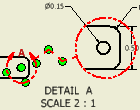
You can create and place a detail drawing view of a specified portion of a view, assigning any scale to the view.
What's New: 2023
In Inventor, if creating a detail view of a presentation with trails, the trails are visible in the view, but can be turned off if needed.
After you place it, the detail view is proportional to the fence size. The fence shape is the same for the parent view and the detail view.
Create a Detail View
- On the ribbon, click
Place Views tab
 Create panel
 Detail
 .
.
- Click to select an existing view as the parent view.
- In the Detail View dialog, set the view identifier, scale, and visibility of the view label. If needed, click Edit View Label and edit the detail view label in the Format Text dialog.
- (Optional) Edit the view identifier as follows:
- To reposition the view identifier on a parent view, pause the cursor over the view identifier. When the cursor icon displays a letter A, click and drag the view identifier around the shape perimeter.
- To edit the view identifier in the parent view, right-click the view identifier, and click Text.
- Set the display style, and fence shape for the detail view.
- Fence Shape. Specifies Circular or Rectangular fence shape.
- Display Full Detail Boundary. Displays a full boundary (circular or rectangular) around the resulting detail view.
- Display Connection Line. Displays a connection line between the fence and the full boundary in the detail view.
- Specify Cutout Shape to specify the type of the cut line as Jagged (the default type for both fence shapes) or Smooth. If you select Smooth, specify whether to display full boundary for the detail view, and whether to add a connection line between the detail view and the detail boundary in the parent view.
- In the graphics window, click to indicate the center of the appropriate detail, move the cursor, and then click to indicate the outer boundary of the detail.
- Move the preview to the appropriate location, and then click to place the view.
Edit a Connection Line

You can add, move, or delete a connection line vertex. If you drag a detail view to a different sheet from the parent view, the connection line is deleted and cannot be created.
- Right-click the detail view annotation (the detail boundary or the connection line).
- Do any of the following:
- To add a vertex to the connection line, choose Add Vertex.
- To move a vertex, click a point on the connection line to add the vertex, and then move the new vertex to the new position.
- To remove a vertex, right-click the vertex, and choose Delete Vertex.
Attach a Detail View Boundary to its Parent View
When you place a detail view, the boundary definition is not attached to the parent view. You must attach the boundary definition to a vertex in the parent view to associate it with a specific location.
The attached detail view definition cannot be moved and maintains its association to the specified vertex if the model file is updated.
- Right-click the detail view definition, then select Attach.
- Select the attachment vertex.
Detach Detail views
Detaching a detail view boundary from its parent view lets you redefine the view.
- Right-click the detail view boundary definition, and then select Attach.
- Click anywhere in blank space within the drawing.
Edit the Detail View Boundary
You can change the shape and appearance of the detail view boundary.
- Right-click the detail callout, click Edit Detail Properties.
- Specify the Fence Shape, Circular or Rectangular.
- Specify the Cutout Shape and its parameters:
- Display Full Detail Boundary. Enables when using the smooth edges option.
- Display Connection Line enables when the Full Detail Boundary is selected. Creates a connection line between the detail view and the detail boundary in the parent view.
Set the Display for the Detail View
The default display type for a detail view the same as its parent view. You use Display in the Detail View dialog to change display style.
- Click one of the options:
-
 Shows hidden lines.
 Removes hidden lines.
-
 Specifies shaded rendering.
-