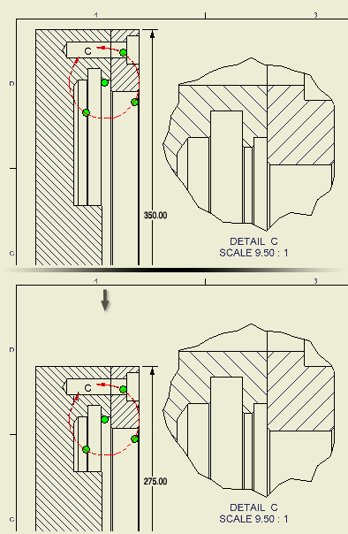
Detail views provide circular and rectangular shapes of detail profile; You can select the Jagged (the default type for both shapes) or Smooth cutout lines.
If you select the Smooth cutout line, you can choose to display a full boundary (circular or rectangular) around the resulting detail view. You can also create a connection line between the fence and the full boundary in the detail view. All three annotation objects (the fence, the boundary, and the connection line) form one annotation object.
The default appearance of the detail view boundary, arrows, label text style, and orientation of the leader text is specified in the View Annotation style.
Detail Views Attached to Points on Parent Views
The Attach command associates detail view definitions with the parent view in the drawing environment. If the dimensions or positional relationships of the parent view geometry are altered, the attached view definition remains attached to and moves with the user-specified attachment vertex.
The view definition maintains its relative position to the parent view. A pin symbol appears next to each attached view or symbol in the browser.

You can use endpoints, center points, and midpoints for the attachment vertex of the view definition. You can also delete the attachment.
When you copy the parent view and attached view definition to the same sheet, to another sheet, or to a different drawing, the attachment relationship is preserved.
You can select multiple view definitions and attach them to a parent view in one operation. Each view definition shares a single attachment vertex on the parent view. You can then redefine the attachment vertex for each instance, as needed.