ViewCube is used to reorient the current view of a model. You can reorient the view of a model with the ViewCube tool by clicking pre-defined areas to set a preset view current, click and drag to freely change the view angle of the model, and define and restore the Home view.
Reorient the Current View
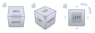
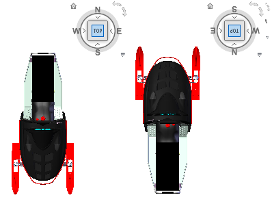
The ViewCube tool provides twenty-six defined parts to click and change the current view of a model. The twenty-six defined parts are categorized into three groups: corner, edge, and face. Of the twenty-six defined parts, six of the parts represent standard orthogonal views of a model: top, bottom, front, back, left, and right. Orthogonal views are set by clicking one of the faces on the ViewCube tool.
You use the other twenty defined parts to access angled views of a model. Clicking one of the corners on the ViewCube tool reorients the current view of the model to a three-quarter view, based on a viewpoint defined by three sides of the model. Clicking one of the edges reorients the view of the model to a half view based on two sides of the model.
You can also click and drag the ViewCube tool to reorient the view of a model to a custom view other than one of the twenty-six predefined parts. As you drag, the cursor changes to indicate that you are reorienting the current view of the model. If you drag the ViewCube tool close to one of the preset orientations and it is set to snap to the closest view, the ViewCube tool rotates to the closest preset orientation.
The outline of the ViewCube tool helps you identify the form of orientation it is in: standard or fixed. When the ViewCube tool is in standard orientation, not orientated to one of the twenty-six predefined parts, its outline is displayed as dashed. The ViewCube tool is outlined in a solid continuous line when it is constrained to one of the predefined views.
Roll a Face View
When you view a model from one of the face views, two roll arrow buttons are displayed near the ViewCube tool. Use the roll arrows to rotate the current view 90 degrees clockwise or counterclockwise around the center of the view.
Switch to an Adjacent Face
When the ViewCube tool is active while viewing a model from one of the face views, four orthogonal triangles are displayed near the ViewCube tool. You use these triangles to switch to one of the adjacent face views.
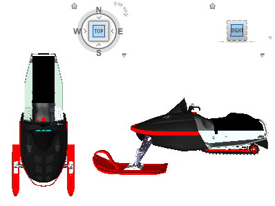
Front View
You can define the Front view of a model to define the direction of the face views on the ViewCube tool. Along with the Front view, the up direction of a model is also used to define the direction of the face views on the ViewCube tool.