Create a Snap Fit from 2D Sketch Points
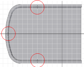
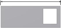
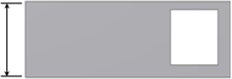
Before starting, create or import a thin-walled part and build a 2D sketch with points that correspond to the Snap Fit placements. 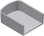
- Click 3D Model tab
 Plastic Part panel Snap Fit
  .
. - In the Shape tab of the Snap Fit dialog box, choose Placement > From Sketch and then choose a snap fit style:
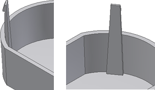
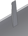
- Cantilever Snap Fit Hook
 .
. 
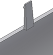
- Cantilever Snap Fit Loop
 .
. 
- Cantilever Snap Fit Hook
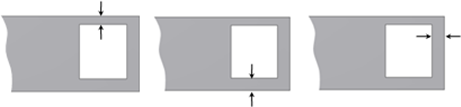
- Using the Centers selector
 and the Hook Direction or Catch Direction selector
  , set the center point and hook or catch direction. Note: Points created using the Center Point switch are automatically selected.The Hook Direction selector provides four arrows, at 90-degree intervals. The directions are aligned with the XY axis of the sketch plane. Click the hook direction arrow to orient each hook properly. Use Flip to switch the direction, which initially corresponds to the sketch plane normal.
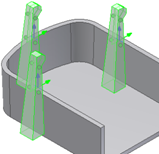
- If the part file has more than one solid body, use the Solid selector
 to choose the target body.
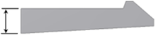
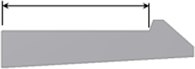
 - Choose whether to extend or stop the snap fit beam:
- Extend selected:
- Extend deselected:
- Extend selected:
- For Cantilever Snap Fit Hooks, specify the hook and beam parameters in their tabs of the Snap Fit dialog box, or use the manipulators until the desired shape is reached.
Note: To facilitate the selection of the directions, shape manipulators are not active when the hook direction is down.
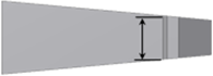
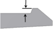
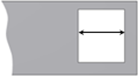
Beam tab- Beam Thickness at the Wall
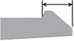
- Beam Length
- Beam Thickness at the Hook
- Beam Width at the Wall
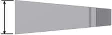
- Beam Width at the Hook
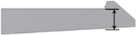
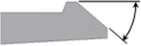
Hook tab- Hook Tip Length
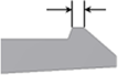
- Hook Undercut Depth
- Hook Length
- Hook Retention Face Angle
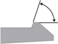
- Hook Insertion Face Angle
- Beam Thickness at the Wall
- For Cantilever Snap Fit Loops, specify the clip and catch parameters in their tabs of the Snap Fit dialog box. Clip tab
- Clip Length
- Clip Width
- Beam Thickness at the Wall

- Beam thickness at Top
Catch tab- Catch Width at the Sides and Top
- Catch Opening Length
- Clip Length
- Click OK.
Create a Snap Fit from a 3D Point
Before starting, create or import a thin-walled part. The goal is to place a Snap Fit feature on the circular edge at a position that is not convenient for the “on sketch” positioning style. For example, use a point on the edge where the hook direction is unlikely to be aligned with a sketch X or Y axis.
Build the construction elements and a 3D work point on the internal wall edge at the position where the Snap Fit is desired. For example, the 3D work point can be the end of a line that is tangent to the internal edge. The hook direction can be a work axis defined by the 3D work point and the center of the circular edge. 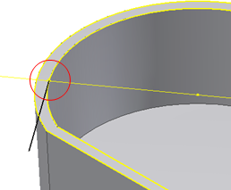
- Click 3D Model tab Plastic Part panel Snap Fit .
- In the Shape tab of the Snap Fit dialog box, choose Placement On Point and then choose the Cantilever Snap Fit Hook or Cantilever Snap Fit Loop snap fit style.
- Using the Centers selector , select the 3D work point for the center point.
- Using the Direction selector , select the face for the direction.
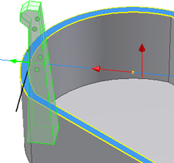
- Using the Hook Direction or Catch Direction selector , select the work axis as the hook or catch direction.
- Adjust the Shape, Beam, and Hook or Shape, Clip, and Catch parameters as desired and click OK.