When you enter the Frame Analysis environment and start a new analysis, the assembly you create with Content Center frame members or Frame Generator automatically converts into a simplified model of beams and nodes.
In the assembly, the frames axes are sometimes not aligned. To get a valid frame model, frame analysis uses the following rules during conversion:
-
Section modifications like chamfer, radius, and holes are ignored on frame sections.
-
Assembly modifications such as Move Face are ignored.
-
If a part is not created in global directions, an error message displays and the part is not converted. Only parts with sketch planes parallel to origin planes are supported.
-
Invisible and suppressed components are not converted to Frame Analysis. They are not visible in the Frame Analysis browser and in the graphics window.
Sometimes you update a source assembly where you suppress or change the visibility of components. In that case, when you enter the Frame Analysis, earlier converted beams and nodes are removed to reflect the actual state of the assembly.
Beams and Nodes
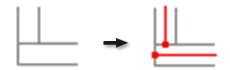
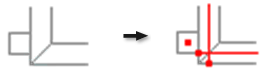
Frames in the frame assembly are converted to Frame Analysis beams (positioned on frame axes) with starting and ending nodes. Contacts among beams are also detected when you create a simulation. When beams are intersecting, they are firmly connected (without adding any connection objects) during the automatic conversion. When the distance between two beams is smaller than sizes of sections multiplied by tolerance, then rigid link connection is created between nearest points.
Tolerance is specified in the Frame Analysis Settings dialog box, Beam Model tab. It is defined as the sum of distances from the gravity of both beams.
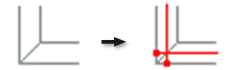
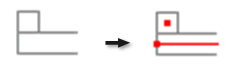
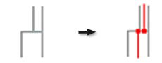
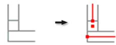
Here are examples of misalignments of neighboring beam centerline axes and how beams ![]() and nodes
and nodes ![]() are created during automatic conversion to Frame Analysis:
are created during automatic conversion to Frame Analysis:
 |
 |
 |
 |
 |
 |
 |
 |
 |
 |
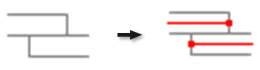
Rigid Links
When the distance between two beams is smaller than sizes of sections multiplied by tolerance, then rigid link connection is created between nearest nodes.
The range of valid inputs is from -100 % to 500%. If you set the value to 0, the beams must be positioned immediately next to each other. Due to an inaccuracy, it is possible that even beams next to each other are not connected. Therefore the default value is set to 2. Positive values create rigid links between beams that have gaps between them, such as Gap weld. Negative values indicate that there must be an intersection between beams to create rigid links.