Using the Manage tab  Author panel Create iPart command, you can prepare tube and pipe iParts for authoring and publishing to the Content Center Library. Each part that is transformed to an iPart Factory contains its own iPart Author table. Units of measurement for the part are set according to the selected standard. To view the Units setting, select Tools tab Options panel Document Settings Units tab.
When a tube and pipe iPart is prepared:
- Use the Parameters command on the Part Features tab to verify the model parameters and user parameters that are used in the iPart. It is recommended that you use model equations to define the part parameters so that multiple part occurrences specified in the iPart Authoring table can dynamically update in proportion.
- Double-click Table in the Model browser to open the iPart Author table. Verify all part occurrences that are defined for the iPart. Each row in the iPart Author table represents a part occurrence for the part family to publish to the Content Center.
- If you need to customize the schedule number and pipe length of the part when placed from the Content Center at a later time, specify them as Custom Parameter Column in the iPart Author table before authoring. Click the column head to select the entire column, right-click, and then select click Custom Parameter Column.
iPart guidelines for defining custom tube and pipe styles using published parts
After tube and pipe iParts are authored and published to the Content Center Library, you can use them to create custom tube and pipe styles. For creating, authoring, and publishing iParts, be aware of the following guidelines:
- Some tube and pipe style settings are defined while authoring and publishing parts to the Content Center Library, others are assigned as part properties. These properties include: Part material property, standard specification, and nominal sizes.
- To create a new style based on custom conduit parts and fittings, they must first exist in the Content Center Library. Conduit parts and fittings are not created for you automatically. Author and publish the needed fittings to the Content Center Library. Once authored and published, define the new style to match the properties of the published fittings. Note: If you need to use published parts to define tube and pipe styles, you must specify the Standards Organization and Standard family properties during publishing. They are the key style criteria to filter out library parts in the Tube & Pipe Styles dialog box.
- The gender, end treatment, and nominal diameter are verified while routing.
- If a published part uses the default material, select the asterisk (*) for material.
- If defining a tube and pipe style with a given nominal diameter, that nominal diameter must be a row in your published iPart Author table to be able to use that part. For example, if the authored part did not have a row specifying 1/2 ND, the Tube & Pipe Styles dialog box does not find the part.
- Define custom standards while publishing to the Content Center Library so that they appear in the Tube & Pipe Styles dialog box, General tab, Standards list. If the standard is not important, use the asterisk (*) for the standard style setting.
Part modeling guidelines
Keep these guidelines in mind as you create tube and pipe iParts for authoring and publishing:
- Keep sketches as simple as possible.
- Use existing work features whenever possible instead of creating new ones. For example, use the existing XY, YZ work planes, rather than creating your own.
- Use centerlines to get needed diameter dimensions in the part.
iPart guidelines and requirements
The iPart Author table must contain a column for each parameter that must change to properly represent all the sizes of the part. For example, if the part contains threads, you must specify the columns for threads.
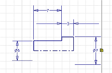
Conduit iParts must contain these five columns. The column names are unimportant. The ND, SN, OD, ID, and PL are parameter columns:
|
ND |
Nominal size of the pipe. The Nominal Diameter (ND) column is critical within Autodesk Inventor Tube & Pipe for matching compatible part sizes. It must contain unitless values for standard dimensions, such as 1/2, or 3/4. Examples for metric dimensions include M15, M20, and so on. It should not be specified as 1/2 in, 1/4 in, 15 mm, 20 mm. |
|
SN |
Schedule number for different thickness |
|
OD |
Outside diameter |
|
ID |
Inside diameter |
|
PL |
Pipe length |
Fitting iParts must include ND. Reduced fittings require an ND column for each nominal diameter the fitting has. For other (not reduced) fittings, specify only one ND column. This must be a primary key.
Fitting size intervals
Fitting size intervals depend on the part materials as listed in the following table:
|
Material |
Minimum/Maximum Size (in) |
Minimum/Maximum Size (mm) |
|
Cast (Gray) Iron |
1/4 - 4 |
DN 10 - 100 |
|
Cast Brass/Bronze Copper |
1/4 - 4 |
DN 10 - 100 |
|
Flanged Steel |
1 - 6 |
DN 25 - 150 |
|
Forged Steel (Threaded) |
1/8 - 4 |
DN 6 - 100 |
|
Forged Steel (Socket) |
1/8 - 4 |
DN 6 - 100 |
|
Wrought Steel |
1/2 - 6 |
DN 15 - 150 |
|
Press Fit Steel |
1/2 - 2 |
DN 15 - 50 |
|
Stainless Steel |
1/2 - 6 |
DN 15 - 150 |
|
PVC |
1/2 - 6 |
DN 15 - 150 |
|
CPVC |
1/2 - 6 |
DN 15 - 150 |
Set the editing scope for iPart factory and members
Autodesk Inventor provides the iParts iAssemblies tool to switch the editing scope when you are working with a tube and pipe iPart factory.
Depending on your design needs, do either of the following:
- If you need to make changes throughout the iAssembly factory, select Tube and Pipe tab iPart/iAssembly panel Edit Factory Scope

- If changes are on the member base, select Tube and Pipe tab iPart/iAssembly panel Edit Member Scope
 . Using the iPart table in the Model browser, you can activate an appropriate part member and make changes.