Describes how you can stack, format, and use properties in text.
Text content, attributes, and properties are set and edited in the Format Text dialog box. Use the Format Text dialog box to:
- Add or edit notes in drawings or text in sketches.
- Specify text attributes for title blocks, borders, datum identifiers, and sketch symbols.
- Add or edit text for dimensions, view labels, hole notes, hole tags, and chamfer notes.
- Insert model parameter references in text. When property values change, text that contains the property updates with the new values.
- Insert iProperty text property references in text. When the text property values change, text containing the text property updates with the new values. Available for all drawing text.
For the current drawing, you can change the layer on which text is placed. On the Annotate tab, Format panel, click the arrow to show the layers list, and select the layer name.
Text Stacking
Text in drawings can be stacked in three different formats: Horizontal fraction, diagonal fraction, and tolerance.
The text stacking functionality is available in the following types of drawing annotations:
- Texts
- Leader texts
- Chamfer, bend, punch, thread, and hole notes
- Dimensions (stacking is controlled by the dimension style)
- Hole, bend, punch and generic tables, and parts lists (stacking is controlled by column settings for numeric columns)
Manual Stacking
To stack text, type a valid stacking sequence in the text field. It consists of one or two strings and a valid stacking trigger. Then select the sequence, right-click and choose Stack.
Stacking triggers are: / (solidus), # (number sign), and ^ (circumflex accent).
Neutral characters are: space, new line return, and tab.
Correct formats for stacked numbers are: 1/2 (results in a horizontal fraction), 1#2 (results in a diagonal fraction), 1^2 (results in a tolerance stacking), ^2 (results in a subscript), 2^ (results in a superscript).
|
Examples of correct stacking format: The left column shows texts in the Format Text dialog box. Strings to be stacked are marked gray. The right column shows the final appearance of texts in the drawing (after stacking is applied). 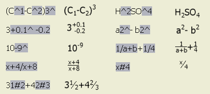 |
AutoStacking
When you type a fractional number (with a valid stacking trigger) followed by a neutral character in the text field, the AutoStack Properties dialog box is displayed by default. After you set the options and click OK in the dialog box, the text is stacked with respect to the selected AutoStack options.
AutoStacking is available in the Format Text, Edit Dimension, Edit Bend Note, Edit Punch Note, Edit Hole Note, Edit Chamfer Note, and Edit Thread Note dialog box.
Text Styles
Autodesk Inventor provides a variety of text styles for documenting drawing views. With text styles you can:
- Receive nearly identical translation of AutoCAD drawings into Autodesk Inventor.
- Predefine the styles needed for documenting designs.
- Move styles between drawings.
In Text Styles, you can define the properties of the text styles used in a drawing. You can choose one of the default text styles or create your own. Options for defining text styles include:
- Text color
- Text stretch
- Font name and size
- Line spacing
- Bold, italics, and underline
- Text rotation
- Text placement justification
After you create text in a drawing, you can edit it to change its content, attributes, or rotation.
Clipping cross lines around text
Leader lines and hatching clip around bounding boxes of text objects. If line or hatch clipping does not update automatically, select the drawing view, and click Update
 on the Quick Access toolbar. Alternatively, edit or move the drawing annotation to refresh its display.
Physical Properties in Drawing Text
Select the Physical Properties - Model property type in the Format Text dialog box to add the model Mass, Density, Volume, and Area in text.
If the displayed value of a physical property is N/A, physical properties of the model are out of date. To update the model, use the Update Mass Properties command.
Notes:
- All values of physical properties are displayed with the unit string. Units are controlled on the Unit tab of the model Document Settings.
- The calculation of physical properties includes quantity overrides and cosmetic welds.
- Mass properties are provided for members of iAssemblies.
- Mass properties are provided for each model state.
Tips:
- To improve performance, we recommend that you migrate parts and assemblies to the latest release file format before you use physical properties in drawing texts.
- To maintain physical properties up to date when the model is saved, select the Update Physical Properties on Save option in the Application Options dialog box.
Sheet Metal Properties in Drawing Text
Use the Format Text dialog box to insert sheet metal iProperties in drawing texts. Select Sheet Metal Properties from the Type list. Then from the Property list, select the property to insert.
Sheet Metal Properties include the following iProperties:
- Flat Pattern Extents Area
- Flat Pattern Extents Length
- Flat Pattern Extents Width
Custom Parameters in Drawing Text
If a model includes user parameters, you can add them to text in the drawing.
To add a user parameter to text, in the Format Text dialog box, select a source model from the Component list. Then select User Parameters from the Source list, and select a user parameter from the Parameter list. Click Add Parameter to insert the parameter in the editing field.
