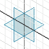
Every part and assembly file has reference planes; they are hidden work planes that intersect at the origin of the XYZ coordinates.

When the reference planes are set to display, they are visible in both wireframe and shaded displays. To resize a reference plane, pause over one of its edges until the Move or Drag symbol appears, then drag a corner to resize it or drag one of its edges to move it. To sketch on a reference plane, select it and then click Sketch.
You can create sketches and construct features anywhere in the graphics window, but most parts require a reference point in space. It can be arbitrary, but it is established so that all features update relative to that point. For example, you can set the center point at the intersection of the reference planes and position it with a Fix constraint or use the Project Geometry command to project the center point onto the sketch plane.