Work features include work planes, work axes, and work point.
Work Planes
- A part face is not available as a sketch plane for sketching new features.
- An intermediate position is required to define other work planes (for example, at an angle to a face at an offset distance).
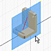
Work planes can be placed at any orientation in space, offset from existing faces, or rotated around an axis or edge. A work plane can be used as a sketch plane and dimensioned or constrained to other features or components. In an assembly, you can create a work plane between two planar faces on separate components.
Place work planes at the center of cylindrical shapes and use them to anchor parametric dimensions between cylindrical features.
Each work plane has its own internal coordinate system. The order in which geometry is selected determines the origin and positive directions of the coordinate system axes.
In a part, a work plane can be created in-line while you are using another work feature command. The Work Plane command terminates as soon as the work plane is created.
In an assembly, you define work planes that reside in the assembly, not in a part model. You can create a work plane mid-way between planar faces on a single part while editing the part. Midpoints can’t be selected in an assembly.
Work Axes


A work axis is a construction line of infinite length that is parametrically attached to a part. Use work axes when creating features and assemblies to mark symmetry lines, centerlines, or distances between revolved feature axes.
You can create a work axis on the following types of geometry:
- A linear edge.
- A sketch line.
- A 2D sketch line.
- A 3D sketch line.
- A line and plane to create a work axis coincident with the line projected onto the plane along the normal of the plane.
You can also place work axes along the axes of circular features such as bosses, shafts, or holes.
In a part, work axes can be created in-line as input to other work feature commands.
In an assembly, a work axis is constrained relative to an existing component.
In drawings, use work axes to project geometries of automatic centerlines and center marks.
Work Points
In a part file you can select model vertices, edge and axis intersections, intersections of three nonparallel faces or planes, and other work features to use as work points. You can also create work points as input to other work feature commands that require you to select a point.
In an assembly file, work points can be created at the intersection of part faces, edges, vertices, and work geometry that span hierarchical levels in the assembly.
Work points can be placed on holes and cuts in part faces, model surfaces, construction surfaces, and base surfaces. When Loop Select Mode is active, you can place a work point on one or more closed loops.
Work points can be placed or projected onto part faces, linear edges, or onto an arc or circle. Work points can be constrained to the center points of arcs, circles, and ellipses.
- Mark shaft and pattern centers
- Define coordinate systems
- Define planes (three points)
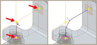
- Define 3D paths
When creating 3D sweeps, you can place a work point at the intersection of work axes and work planes. You click work points and vertices of existing parts to define the path of the sweep.
Work points can be grounded or ungrounded. Grounded work points have all degrees of freedom removed and are fixed in space. Ungrounded work points can be repositioned by dimensions or constraints.
Work Features and Drawings
You can reference work features in drawing views. To learn more about how to reference work features in drawings, see To Show or Hide Work Features in Drawing Views.