Specifies the part type, number of connections, end treatment, required part parameters, engagement, and optional ISOGEN properties for tube and pipe iParts or normal parts to author.
|
Access: |
With a tube and pipe iPart or a normal part open, click Manage tab  Author panel Tube and Pipe Author panel Tube and Pipe |
Generic authoring parameters
|
Type |
Specifies the part type to author from the available list. The selected type determines the root category to which you can publish the part in the Content Center.
Tip: If you are authoring a cap, elbow, tee, or cross, click the appropriate connection image.
|
|
Connections |
Specifies the number of connections for the part being authored. Each part type defaults to a connection number. If you do not use the default number of connections, set a new value in the Connections list. |
|
Connection Number |
Specifies the connection to define. The number of connections changes dynamically depending on the quantity specified for the part being authored. Click the number representing the connection to set. Red numbers indicate that the connection criteria have not been satisfied. Black indicates the connection has the necessary information for publishing. |
|
Angle |
Read-only display of the angle value between the two primary connections. |
|
End Treatment |
Sets the end treatment used for the component. An end treatment can be defined for each connection in the part. Click the arrow to select an end treatment from the list. |
|
Parameter Mapping |
Maps each required parameter listed to the appropriate key parameters specified in the iPart table. Sets parameters for the component. Click the arrow to select a parameter from the list, and then map each one to the appropriate iPart table column. For example, the Nominal Size parameter may be mapped to a column named ND while a Schedule Number parameter is mapped to SN. All listed parameters must be mapped. To author a fitting iPart, Nominal Size is the only required parameter. To author a conduit iPart, required parameters includes:
Note:
|
|
Connection |
Sets the connection point and axis information, specifies the type of connection, and flips the axis direction if needed. Female sets the type of connection and the direction of the displayed work axis. Clear the box for male connections. Note: Branch fittings have their particular connection information to define.
|
|
Engagement |
Specifies a range minimum and maximum that determines how the pipe is inserted into a fitting. Max sets a value for the maximum engagement using any of the following three ways:
Min % of Max sets a value for the minimum engagement position, which is always a percentage of the MaxEP value. Note: Branch fittings do not need to specify the engagement information for the last connection number.
|
|
ISOGEN Properties |
Specifies the ISOGEN property settings for the part being authored. Type specifies the piping component type property required by ISOGEN .pcf files. Click the arrow to select from the list. ISOGEN SKEY lists the four-character symbol keys that consists of the two-character pairs for part type and their valid end types. The SKEY is used as part of ISOGEN endpoint input. Click the arrow to select from the list. If wild cards **, @ or + are included in the SKEY, select the wild card value from the next drop-down list. Note: Type and ISOGEN SKEY properties must be set for the .pcf file to work.
Character Keys lists the values for SKEY wild cards, if appropriate. Click the arrow to select from the list. Wild card values include:
ITEM-CODE specifies the parameter to use for the manufacturer's item-code for the selected part. For iParts, it selects the ITEM-CODE column in the family table and maps it to the item-code property. For non-iparts, enter the needed code based on the manufacturer's data. You can also click the arrow to map the item code to other parameters. ISOGEN Description provides a manufacturing description of the selected part. Click the arrow to select from the list, or enter the needed description. Note: To add the item-code property to existing data, use the Content Center Editor.
|
Specific parameters for normal parts
Once a normal part is authored and published into the Content Center, the part family only has one part member. The authoring process does not need to specify the table mapping but must define the nominal diameter:
|
Nominal Size |
Specifies the fixed nominal size of the normal part being authored. Normal parts can only be authored and published as fittings. Note: This setting is available only when you are authoring a normal part.
|
Specific parameters for branch fittings
A branch fitting may own as many connections as you need, typically two connections. The last connection number on a branch fitting is typically used to mate to the desired conduit part so it requests a series of particular authoring parameters.
|
Parameter Mapping |
The generic branch fitting and butt welded fitting require the key parameters of Min Nominal Size and Max Nominal Size. They conform to the specific industry standard, typically designated to the nominal size of the mating pipe. |
|
Connection |
Sets the connection point and axis information, specifies the type of connection, and flips the axis direction if needed. Note:
Note:
|
|
Cut |
Specifies the profile that is used to cut a hole in the mating conduit part. Cut Mating Pipe determines whether placing a branch fitting will cut a hole on the conduit part. Note: If no profile is satisfying, it is recommended that you first create a closed 2D sketch manually.
|
|
ISOGEN |
Selects OLET from the Type list, and then specify an appropriate ISOGEN Skey in the list, and an ITEM-CODE and ISOGEN Description. |
The following images illustrate the key parameters for authoring a sample branch fitting:
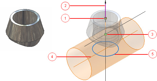
1 - Connection point for Connection Number 1; 2 - Connection axis for Connection Number 1; 3 - Mating Point for Connection Number 2; 4 - Pipe Axis for Connection Number 2; 5 - Cut Profile