What's New: 2021
Emboss or Engrave a Face or Plane
The Emboss feature raises or recesses a profile relative to the model face by a specified depth and direction. The embossed area can provide a surface for a decal or painting. A recessed embossed area can provide clearance for another component in an assembly.
Start with a part file that contains a 2D sketch of the profile you want to emboss or engrave.
- Click
3D Model tab
 Create panel
 Emboss
 .
.
- Using the Profile selector, click in the graphics window to select one or more profiles (sketch geometry or text) to emboss or engrave.
Tip: To make selection easier, turn off automatic projection. In the Application Options dialog box, Sketch tab, deselect Autoproject Edges During Curve Creation.
-
3. Choose an emboss type:
- Emboss From Face. Raises the profile area.
- Engrave From Face. Recesses the profile area.
- Emboss/Engrave From Plane. Adds and removes material from the model by extruding both directions or one direction from the sketch plane. If both directions, material is removed and added, depending on the position of the profile relative to the part.
- Specify the options associated with the type of emboss you’re performing:
- Depth. (Emboss From Face and Engrave From Face) Specifies the offset depth to emboss or engrave the profile.
- Taper. (Emboss/Engrave From Plane) Specifies the degree of taper. The angle is positive toward the face of the model, allowing draft for removing the part from a mold.
- Top Face Appearance. Specifies an appearance for the face of the embossed area but not its lateral sides. In the Appearance dialog box, click the down arrow to show a list. Scroll through the list or type the first letter to locate the desired appearance. Click OK.
- Direction. Specifies the direction of the feature. Useful if the profile is on a work plane offset from the model face.
- Wrap to Face. (Emboss From Face and Engrave From Face) Specifies if the profile is wrapped on a curved face. Limited to a single face, not a seamed face. The face can be planar or conical only, not a spline. Clear the checkbox to project the image to the face instead of wrap. If the profile is large relative to the amount of curvature, the embossed or engraved area distorts slightly as it projects to the curved face. The wrap stops when a perpendicular face is encountered.
- Click OK.
Edit an Emboss or Engrave Feature
For best results, follow this sequence:
- If necessary, in the browser, click the Emboss feature to expand its contents.
- Right-click the Sketch icon, and then click Edit Sketch.
- In the active sketch, right-click the text, and then click Edit Text.
- In the Format Text dialog box, change text as necessary, and then click OK.
- Use other sketch commands as necessary to change other sketch geometry, and then right-click, and click Finish Sketch.
- In the browser, right-click the emboss feature, and then click Edit Feature.
- Click Profile, and reselect new text or sketch geometry to include in the embossed feature. Change any other settings in the dialog box as needed, and then click OK.
The embossed feature updates with the changes to the sketch geometry and text.
Create a Decal on a Surface or Part
To create decals, you insert an image in a sketch, position it using constraints and dimensions, and then apply it as a decal using the Decal command on the 3D Model tab. The decal feature is applied to an existing model.
- Click
3D Model tab
 Create panel
 Decal
Decal
 .
.
- Sketch behavior:
- If there is only one visible sketch, it is automatically selected.
- If there are multiple visible sketches, no automatic selection occurs. You are prompted to select the desired sketch. If you have multiple visible sketches for decals, click the property panel advanced setting "Keep sketch visible on ( + )" and use the Apply button to expedite creating decals.
- If there is no sketch, a new sketch is started on a face or workplane which you select.
- Browse to and choose the decal image file.
Tip: Helpful information about images used for the Decal command.
- Right-click the image in the graphics window and use options in the Image Properties dialog box to reorient the image.
- Some file formats support transparent backgrounds (e.g. PNG, BMP, TIFF). Click Use Image Alpha when the image has a transparent background.
- To make the decal background transparent, but the image doesn't have a transparent background, click Use Mask. The background color will be assigned as a transparent value. This requires that the background be one color, not gradient or multi-color. If using a .jpg image, there is often a lot of blending artifacts that will need to be removed before using the image as a decal.
- In the graphics window, click to place the image and then position it as desired. For example:
- Click in the center of the image and drag to move it.
- Click a corner of the image and drag to resize it. The image maintains its original aspect ratio.
- Click an edge to pivot the image.
- Use constraints and dimensions to fix the position and align it to other geometry
- When the image is positioned correctly, click Finish Sketch. The sketch is closed and the Decal command resumes.
- In the Decal property panel, use the following options to select and place the decal:
- Image. Specifies an image to use as the decal. If there is only one image in a visible sketch it is automatically selected. If resized, the image retains its original aspect ratio. Use dimensions and constraints to position the image on the sketch.
- Face. Select the face on which to apply the decal. The decal will flow over adjacent tangent faces when Automatic Face Chain is checked.
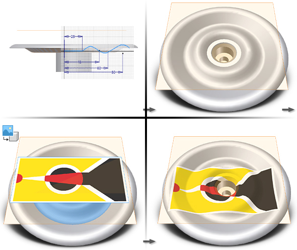
- Wrap To Face. Specifies whether the image is wrapped on one or more curved faces. Clear the checkbox to project the image onto one or more faces without wrapping. Select the box to wrap a decal on cylindrical, toroidal, and other nonplanar faces. The projection is normal to the sketch plane.
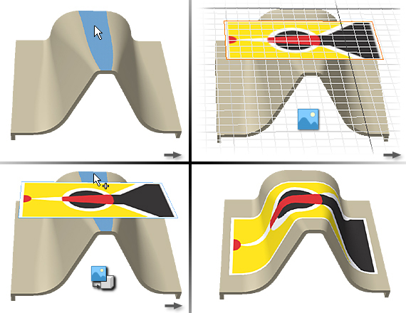
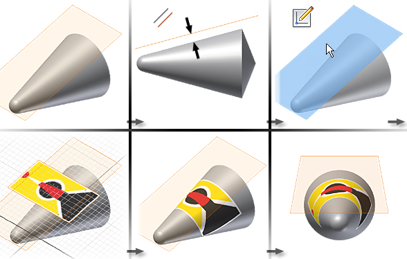
Decal placement with Wrap To Face and Chain Faces selected: Decal placement on a cone with Wrap To Face and Chain Faces selected:
 Decal spanning spline, straight, and arc surfaces with Chain Faces selected:
 Note: The decal image is projected which causes it to distort when applied to an irregular surface or adjacent faces. The closer faces are to being perpendicular, the greater the amount of distortion.
 - When the decal is applied as desired, click OK.
In an existing part file:
To Simulate a Decal on an Assembly Component
When a decal spans a seam across parts in an assembly, create a thin-walled solid part or surface the same size as the decal, apply the decal to the part, then, place and constrain the part in the assembly.
- Create a part file that displays a decal. It should be the shape and size of the full scale decal.
- In the assembly file, right-click and choose Place Component.
- Browse to and select the part file containing the decal.
- Add work features as necessary to assist with decal placement.
- Add assembly constraints to position the decal.
Alternatively, convert an assembly to a derived part, and then apply the decal to the part.
Tip: If you use the decal in multiple assemblies, create iMates to simplify positioning the decal.Tip: If using a surface model, you may want to use an offset value for the face mate or flush constraint.