Sweeps can be created along a path, along a path and a guide rail, or along a path and a guide surface.
What's New: 2020
You can create sweep features in parts or assemblies. However, sweeps with a guide surface or a solid Toolbody are not available in the assembly environment.
Sweep a Toolbody Along a Path
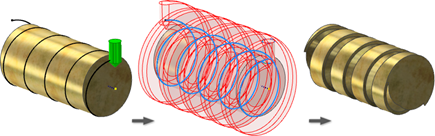
You can use solid sweep to create complex shapes, simulate toolpaths, or to design timing screws. The toolbody is not required to be a revolved or cylindrical body.
Following are some tips for a successful solid sweep:
- Avoid making overlapping segments in your sketches.
- Place the toolbody at the start of the sweep path.
- The path is not required to be G1 (tangent) or G2 (smooth) continuous, but the best results are obtained with G2 continuous paths.
- When you create the toolbody, use the minimum amount of geometry and avoid internal voids. This increases both performance and compute success.
- If the sweep fails to compute, try removing toolbody fillets. In some cases, it may help to add fillets.
- The Helical Curve command creates an associative center axis you can select as the direction vector in an Aligned sweep.
- Before you start the command:
- Create the base solid.
- Create the sweep path.
- Create the solid toolbody, preferably at the start of the sweep path.
- Click
3D Model tab
 Create panel
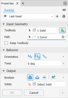
Sweep
Create panel
Sweep
 .
.
If required, enable the Solid Sweep option
 in the property panel.
- Select the solid Toolbody.
- Select a Curve or an Edge to define the Path.
- Choose an Orientation:
 Follow Path
 Fixed
Fixed
 Aligned
- If using the Aligned option, select the axial direction Vector.
- If required, specify the Twist angle. The Twist angle is related to the toolbody, not 3D space.
If required, select the Twist Axis.
The following image shows the effect of a 90 degree Twist angle in an Aligned sweep. The twist angle applied to the toolbody creates a design that can rotate a bottle from horizontal to vertical along the path.
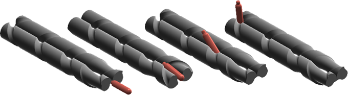
(Model credit: Scott Moyse)
- Specify an Output operation:
Note: The default output with zero or one solid in the model is New Solid. The Output section of the property panel will not display. When there is more than one solid in the model, the following options are presented:
 Join. Adds the volume created by the swept feature to another feature or body. Not available in the assembly environment.
 Cut. Removes the volume created by the swept feature from another feature or body.
 Intersect. Creates a feature from the shared volume of the swept feature and another feature. Deletes material that is not included in the shared volume. Not available in the assembly environment.
 New Solid. Creates a solid body. Each solid body is an independent collection of features separate from other bodies. A body can share features with other bodies. If desired, rename the body.
- Click Ok.
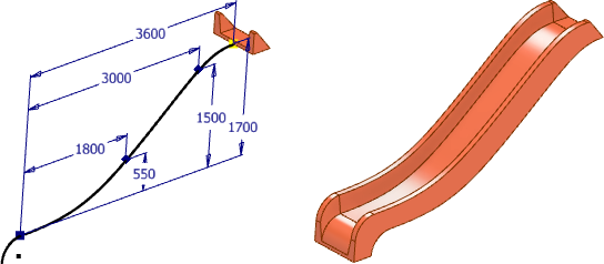
Sweep a Profile Along a Path
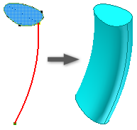
- Sketch a profile and path on intersecting planes. The path must pierce the profile plane. The start point must be located on the intersection of the planes for profile and path.
- Click
3D Model tab
Create panel
Sweep
.
If there is only one profile in the sketch, it highlights automatically. Otherwise, select a sketch profile.
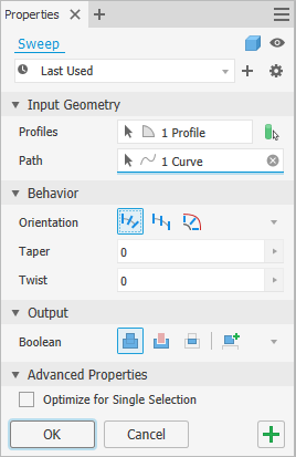
- In the Sweep dialog box, click Profile and then select the profile to sweep.
Tip: When making multiple profile selections, to prevent automatic advance to the next selector, clear the check box for Optimize for Single Selection.
- With the Path selection tool, select a 2D sketch, 3D sketch, or edges of geometry.
Note: If using edges for the path, when the sweep command is completed, the edges project to a new 3D sketch.
- If there are multiple solid bodies, click Solids and then select the participating bodies.
- Specify the Output type:
-
 Solid. Creates a solid feature from an open or closed profile. Open profile selection is not available for base features.
 Surface. Creates a surface feature from an open or closed profile. Functions as a construction surface on which to terminate other features, or a split tool to create a split part, or split a part into multiple bodies. Surface selection is not available for assembly extrusions or primitives.
-
- Choose
Type
Path.
- Choose an Orientation:
 Path. Holds the swept profile constant to the sweep path. All sweep sections maintain the original profile relationship to the path.
-
 Parallel. Holds the swept profile parallel to the original profile.
- For a path sweep oriented to a path, specify Taper and Twist angles.
A positive taper angle increases the section area as the sweep moves away from the start point.
A negative taper angle decreases the section area as the sweep moves away from the start point.
With nested profiles, the sign (positive or negative) of the taper angle is applied to the outer loop of nested profiles; inner loops have the opposite sign.
- Specify an Operation:
Note: The default output with zero or one solid in the model is New Solid. The Output section of the property panel will not display. When there is more than one solid in the model, the following options are presented:
- Join. Adds the volume created by the swept feature to another feature or body. Not available in the assembly environment.
- Cut. Removes the volume created by the swept feature from another feature or body.
- Intersect. Creates a feature from the shared volume of the swept feature and another feature. Deletes material that is not included in the shared volume. Not available in the assembly environment.
- New Solid. Creates a solid body. Each solid body is an independent collection of features separate from other bodies. A body can share features with other bodies. If desired, rename the body.
- Click Ok.
Sweep a Profile along a Path and Guide Rail
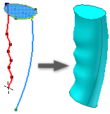
- Sketch a profile and path on intersecting planes. Sketch an additional curve to serve as a rail that controls profile scaling and twist. The path and rail must pierce the profile plane.
- Click
3D Model tab
Create panel
Sweep
.
If there is only one profile in the sketch, it highlights automatically. Otherwise, select a sketch profile.
- In the Sweep dialog box, click Profile and then select the profile to sweep.
- With the Path selection tool, select the path sketch or edges.
- If there are multiple solid bodies, click Solids and then select the participating bodies.
- Specify the Output type:
- Solid. Creates a solid feature from an open or closed profile. Open profile selection is not available for base features.
- Surface. Creates a surface feature from an open or closed profile. Functions as a construction surface on which to terminate other features, or a split tool to create a split part, or split a part into multiple bodies. Surface selection is not available for assembly extrusions or primitives.
- With the Guide Rail selection tool, select the guide curve or rail in the graphics window.
- In the Sweep dialog box, under Profile Scaling options, specify how the swept section scales to meet the guide rail:
- X & Y. Scales the profile in both the X and Y directions as the sweep progresses.
- X. Scales the profile in the X direction as the sweep progresses.
- None. Keeps the profile at a constant shape and size as the sweep progresses. Using this option, the rail controls only profile twist.
- Choose
Type
Path & Guide Rail.
- Specify an Operation:
Note: The default output with zero or one solid in the model is New Solid. The Output section of the property panel will not display. When there is more than one solid in the model, the following options are presented:
- Join. Adds the volume created by the swept feature to another feature or body. Not available in the assembly environment.
- Cut. Removes the volume created by the swept feature from another feature or body.
- Intersect. Creates a feature from the shared volume of the swept feature and another feature. Deletes material that is not included in the shared volume. Not available in the assembly environment.
- New Solid. Creates a solid body. Each solid body is an independent collection of features separate from other bodies. A body can share features with other bodies. If desired, rename the body.
- Click Ok.
Sweep a Profile Along a Path and Guide Surface
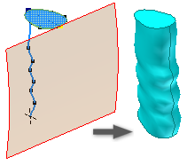
- In a part file, project a curve onto a nonplanar surface to create the sweep path. This surface controls profile twist. Sketch a profile on an intersecting plane. The path must pierce the profile plane.
- Click
3D Model tab
Create panel
Sweep
.
If there is only one profile in the sketch, it is selected automatically. Otherwise, select a sketch profile.
- In the Sweep dialog box, click Profile and then select the profile to sweep.
- With the Path selection tool, select a planar path, non-planar sketch, or edges.
- If there are multiple solid bodies, click Solids and then select the participating bodies.
- Specify the Output type:
-
Solid. Creates a solid feature from an open or closed profile. Open profile selection is not available for base features.
- Surface. Creates a surface feature from an open or closed profile. Functions as a construction surface on which to terminate other features, or a split tool to create a split part, or split a part into multiple bodies. Surface selection is not available for assembly extrusions or primitives.
-
- Choose
Type
Path & Guide Surface.
- With the Guide Surface selection tool, select the surface in the graphics window to control the twist of the swept profile about the path.
- Specify an Operation:
Note: The default output with zero or one solid in the model is New Solid. The Output section of the property panel will not display. When there is more than one solid in the model, the following options are presented:
- Join. Adds the volume created by the swept feature to another feature or body. Not available in the assembly environment.
- Cut. Removes the volume created by the swept feature from another feature or body.
- Intersect. Creates a feature from the shared volume of the swept feature and another feature. Deletes material that is not included in the shared volume. Not available in the assembly environment.
- New Solid. Creates a solid body. Each solid body is an independent collection of features separate from other bodies. A body can share features with other bodies. If desired, rename the body.
- Click OK.
Editing a Sweep Feature
- In the graphics window or the browser, right-click the feature and choose
Edit Feature. You can double-click the browser node to edit the feature.
The property panel displays.
- Change feature defining values, the orientation, or whether it twists.