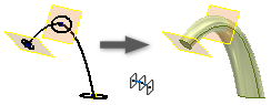
Lofts blend multiple profiles, called sections, and transition them into smooth shapes.
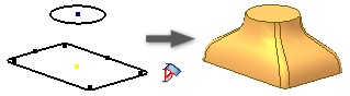
Work from a sketch that represents cross-sections of the loft feature and contains sketch sections on separate planes. In addition to sketched profiles, you can select object faces and points to include as loft sections.
In the Loft dialog box, the Curves tab allows you to choose the sections to include in the loft. Selected sections are identified as sketches, edges, or points.
The Conditions tab defines boundary conditions for end sections and for outermost rails. Apply conditions to rails of an open section loft that borders adjacent surfaces, or a loft with sections that begin or end at a point. The boundary conditions control the shape of the loft body near its boundary.
In the Transition tab, mapping points, rails, centerlines, and section vertices define how segments of one section map to the segments of the section before and after it.
Create a Loft Using Rail Guides
- Click
3D Model tab
 Create panel
Loft
Create panel
Loft
 .
.
- On the Curves tab of the Loft dialog box, click in Sections, and then select, in sequence, the sections you want to blend.
If you select multiple sections on any plane, they must intersect.
If more than one loop is in a sketch, first select the sketch and then select the curve or loop.
For solid lofts, select closed curves in 2D or 3D sketch, or a closed face loop (continuous edges surround a face) of a part face.
For surface lofts, select open or closed curves in 2D or 3D sketch, or a face loop of a part face. Pause the cursor over an edge in the loop, right-click, and then click Select Other. Cycle through available selections. Or select a set of continuous model edges.Tip: To speed processing, turn off the Preview.
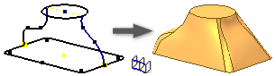
- Click Rails and select one or more 2D or 3D curves. Sections must intersect rails. The loft rails control the loft shape between sections.
- If the part contains multiple solid bodies, click the Solids selector to choose the participating body.
- Specify the Output type:
- Solid
 . Creates a solid feature from an open or closed section.
- Surface
 . Creates a surface feature from an open or closed section. Can be a construction surface on which other features terminate, or as a split tool to create a split part.
- Solid
- (Optional) Choose either or both of the following:
- Closed Loop. Joins the first and last sections of the loft and forms a closed loop.

- Merge Tangent Faces. Merges loft faces and does not create an edge between tangent faces of the feature.
- Closed Loop. Joins the first and last sections of the loft and forms a closed loop.
- Specify an Operation:
- Join
 . Adds the volume created by the lofted feature to another feature or body.
- Cut
 . Removes the volume created by the lofted feature from another feature or body.
- Intersect
 . Creates a feature from the shared volume of the lofted feature and another feature. Deletes material that is not included in the shared volume.
- New Solid
 . Creates a solid body. If the loft is the first solid feature in a part file, this selection is the default. Select to create a body in a part file with existing solid bodies. Each body is an independent collection of features, separate from other bodies. A body can share features with other bodies.
- Join
- On the Conditions tab of the Loft dialog box, specify boundary conditions for your sections and rails. Click the condition icon, select the boundary condition from the list, and specify angles and weights:
- Free Condition
 . Applies No boundary conditions.
- Tangent (G1) Condition
 . Available when the section or rail is next to a lateral surface or body, or when the selection is a face loop. (To project a face boundary automatically, in the Application Options dialog box, Sketch tab, select Automatic reference edges for new sketch.)
- Direction Condition
 . Available only when the curve is a 2D sketch. Measures the angle relative to the section plane.
- Smooth (G2) Condition
 . Available when the section or rail is next to a lateral surface or body, or when the selection is a face loop. Enables curvature continuity for beginning and end loft sections and rails.
- Angle. Represents the transition angle between the section or rail plane, and the faces created by the loft. The default value of 90 degrees provides a perpendicular transition. A 180 degree value provides a planar transition. The range is from 0 to 180 degrees.
- Weight. A unitless factor that controls the appearance of the loft. Determines how far the section shape extends before it transitions into the next shape. Large weight values can result in twisting of the lofted surface and cause a self-intersecting surface. Typical weight factors range from 1 to 20. Large and small values are relative to the size of your model.
Note: The selected sketch or edge highlights in the graphic. - Free Condition
- To modify or map points manually, on the Transition tab, deselect Automatic Mapping and add, edit, or delete point sets and points:
- Point Set. Lists automatically calculated points on each loft section.
- Map Point. Lists automatically calculated points on a sketch, which align sections linearly along the points, and minimize twisting of the loft feature. Points are listed in the order you select sections.
- Position. Specifies position relative to the selected point in unitless values. Zero indicates one end of the line, 0.5 represents the middle of the line, and one indicates the other end of the line.
- Click OK.
Create a Centerline Loft
- Click
3D Model tab
Create panel
Loft
.
If you select multiple sections on any plane, they must intersect.
If more than one loop is in a sketch, first select the sketch and then select the curve or loop.Tip: To speed processing, turn off the Preview.
- On the Curves tab of the Loft dialog box, click in Sections, and then select, in sequence, the sections you want to blend.
- Click Center Line
 and select a 2D or 3D curve to use as the centerline. The centerline holds the loft shape between sections normal to the centerline.
- If the part contains multiple solid bodies, click the Solids selector to choose the participating body.
- Specify the Output type:
- Solid
. Creates a solid feature from an open or closed section.
- Surface
. Creates a surface feature from an open or closed section. Can be a construction surface on which other features terminate, or as a split tool to create a split part.
- Solid
- (Optional) Choose either or both of the following:
- Closed Loop. Joins the first and last sections of the loft and forms a closed loop.
- Merge Tangent Faces. Merges loft faces and does not create an edge between tangent faces of the feature.
- Specify an Operation:
- Join
. Adds the volume created by the lofted feature to another feature or body.
- Cut
. Removes the volume created by the lofted feature from another feature or body.
- Intersect
. Creates a feature from the shared volume of the lofted feature and another feature. Deletes material that is not included in the shared volume.
- New Solid
. Creates a solid body. If the loft is the first solid feature in a part file, this selection is the default. Select to create a body in a part file with existing solid bodies. Each body is an independent collection of features, separate from other bodies. A body can share features with other bodies.
- Join
- To modify or map points manually, on the Transition tab, deselect Automatic Mapping and add, edit, or delete point sets and points:
- Point Set. Lists automatically calculated points on each loft section.
- Map Point. Lists automatically calculated points on a sketch, which align sections linearly along the points, and minimize twisting of the loft feature. Points are listed in the order you select sections.
- Position. Specifies position relative to the selected point in unitless values. Zero indicates one end of the line, 0.5 represents the middle of the line, and one indicates the other end of the line.
- Click OK.
Create a Loft to a Point
- Click
3D Model tab
Create panel
Loft
.
- On the Curves tab of the Loft dialog box, click in Sections, and then select, in sequence, the sections you want to blend.
Point sections must be at the beginning or end of the loft.
If you select multiple sections on any plane, they must intersect.
If more than one loop is in a sketch, first select the sketch, and then select the curve or loop.
- Optionally, specify whether to create a loft with rails, or a centerline. Use the context menu and switch between Sections, Rails, and Centerlines, or change the selection type in the dialog box. Select a single 2D or 3D curve for centerline, or one or more curves for guide rails. Sections must intersect rails, but need not intersect a centerline.
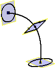
Note: When specifying a centerline with a point, the centerline must pass through the point section and near the middle of the neighboring section
- If the part contains multiple solid bodies, click the Solids selector to choose the participating body.
- Specify the Output type:
- Solid
. Creates a solid feature from an open or closed section.
- Surface
. Creates a surface feature from an open or closed section. Can be a construction surface on which other features terminate, or as a split tool to create a split part.
- Solid
- (Optional) Choose either or both of the following:
- Closed Loop. Joins the first and last sections of the loft and forms a closed loop.
- Merge Tangent Faces. Merges loft faces and does not create an edge between tangent faces of the feature.
- Specify an Operation:
- Join
. Adds the volume created by the lofted feature to another feature or body.
- Cut
. Removes the volume created by the lofted feature from another feature or body.
- Intersect
. Creates a feature from the shared volume of the lofted feature and another feature. Deletes material that is not included in the shared volume.
- New Solid
. Creates a solid body. If the loft is the first solid feature in a part file, this selection is the default. Select to create a body in a part file with existing solid bodies. Each body is an independent collection of features, separate from other bodies. A body can share features with other bodies.
- Join
- On the Conditions tab of the Loft dialog box, specify boundary conditions for your sections and rails. Click the condition icon, select the boundary condition from the list, and specify angles and weights.
For point sections:
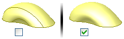
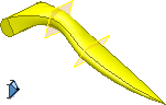
- Sharp Point
 . Available only when the beginning or end section is a point. Applies no boundary condition. Enables a direct transition from an open or closed section to a pointed or cone-shaped tip.
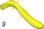
- Tangent
 . Available only when the beginning or end section is a point. Applies tangency. Enables the loft section to transition to a rounded, or dome-shaped point.
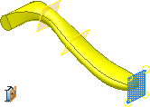
- Tangent to Plane
 . Available only when the beginning or end section is a point. Applies tangency to the point based on a selected plane. Enables the loft section to transition to a rounded dome shape. Select a planar face, or workplane. Not available for use with centerline.
For other sections and rails:- Free Condition
. No boundary conditions.
- Tangent (G1) Condition
. Available when the section or rail is next to a lateral surface or body, or when the selection is a face loop. (To project a face boundary automatically, in the Application Options dialog box, Sketch tab, select Automatic reference edges for new sketch.)
- Direction Condition
. Available only when the curve is a 2D sketch. Measures the angle relative to the section plane.
- Smooth (G2) Condition
. Available when the section or rail is next to a lateral surface or body, or when the selection is a face loop. Enables curvature continuity for beginning and end loft sections and rails.
Note: The selected sketch or edge highlights in the graphic. - Sharp Point
- To modify or map points manually, on the Transition tab, deselect Automatic Mapping and add, edit, or delete point sets and points:
- Point Set. Lists automatically calculated points on each loft section.
- Map Point. Lists automatically calculated points on a sketch, which align sections linearly along the points, and minimize twisting of the loft feature. Points are listed in the order you select sections.
- Position. Specifies position relative to the selected point in unitless values. Zero indicates one end of the line, 0.5 represents the middle of the line, and one indicates the other end of the line.
- Click OK.
Create an Area Loft
- Click
3D Model tab
Create panel
Loft
.
- In the graphics window, select, in sequence, the sections you want to blend.
- In the Curves tab of the Loft dialog box, click Area Loft
 and select a 2D or 3D curve as the centerline. The centerline holds the loft shape between sections normal to the centerline.
Upon selecting the centerline, section dimensions display at each endpoint. They provide the area and position relative to the centerline for each selected section.
To see whether the centerline is normal to the section, use Area Loft. The section dimension points to a section that is normal to the centerline.
In addition to these two sections, you can add placed sections to define cross-sections that control the shape of the loft.
- In the Curves tab of the Loft dialog box, click Placed Sections and click to add one. Move the indicator along the centerline to the point location, and click to add the point. A section dimension displays for each placed section.
- To change the position or size of a placed section, double-click it and do any of the following in the Sections Dimensions dialog box:
- To change or control the position of a section along the length of the centerline, in Section Position, select the appropriate option, and enter a value. To position the section relative to the length of the centerline, use Proportional Distance. To place the section along the absolute distance of the centerline, use Absolute Distance. For example, if the centerline is 16 inches, to create the placed section in the middle of the centerline, enter 8.
- To change or control the scale, select the appropriate Section Size option, and enter a value. To scale the section to match a specified area value, select, and enter a value for Area. Dimensions are relative along the length of the centerline. To scale the section to match a specified area value, select and enter a value for Scale Factor. To tweak the shape of the loft, use Scale factor as an aesthetic design tool.
- Use the Driven Section and Driving Section (Inspection) to define a section. To change the section position and size, select Driving Section. To disable all section size controls, and allow control of only section position, select Driven Section. Typically, you use Placed Sections as Driving Sections.
- Click OK to close the Section Dimensions dialog box.
- Click OK to create the loft.