This Inventor release is full of drawing annotations enhancements.
Weld Annotations
In the Welding Symbol dialog, the Identification Line and Spacer controls are always visible and enable for the appropriate weld specification.
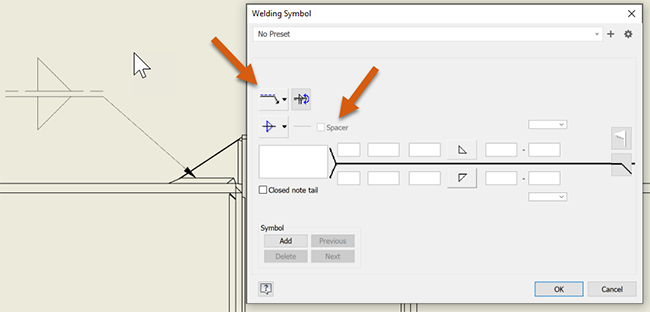
For more information see Weld Annotations in Drawings and Drawing Welding Symbol Reference.
A new "Field Flag Direction" option is added to the Weld Symbol Style and Standard Editor dialog enabling you to set the direction of the field flag. The "Fixed Right" option is set as default for JIS standard and provides the same functionality as in the previous releases. The "Automatic" option is set as default for other standards.

For more information see Style and Standard Editor - Weld Symbol Style Reference.
Edge Weld Symbols now uses the latest available ISO 2553-2019 standard. The symbol is added to the Style Editor and enabled by default for the following standards: ISO, DIN, ANSI, BSI, GB, JIS, GOST (only in weldment).

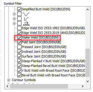
A Stake Weld per EN ISO 2553:2017 is added. The symbol is added to the Style Editor and enabled by default for the following standards: ISO, BSI, DIN, GOST (only in weldment). It is also available for the following standards but not enabled by default: ANSI, JIS, GB, GOST (only in drawing).
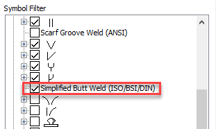
Simplified Butt Weld and Edge Weld Symbols now uses the latest available ISO 2553-2019 standard. The symbol is added to the Style Editor and enabled by default for the following standards: ISO, BSI, DIN, GOST (only in weldment). It is also available for the following standards but not enabled by default: ANSI, JIS, GB.
Updated Surface Finish Collection symbol
Surface Finish Collection symbol is updated per the latest EN ISO 1302:2002 standard.
You also now have the ability to define a Collection Symbol with Surface texture symbol outside a bracket and include all surface texture reference types on the sheet.
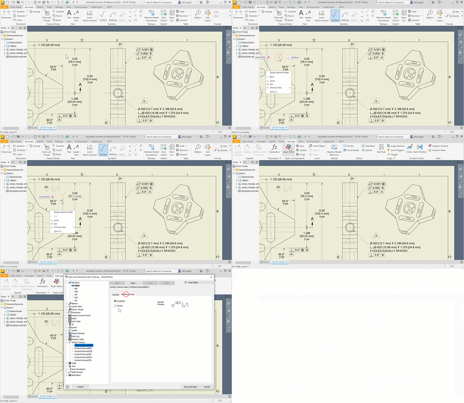
For more information see Add a surface texture symbol.
Insert Parent Assembly iProperties into Leader Text
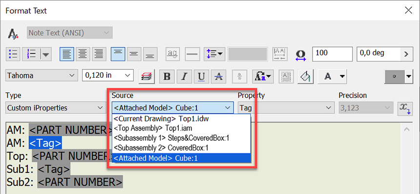
3D and 2D leader text can now include standard iProperties, custom iProperties, and instance properties belonging to parents of the attached part. Previously, only properties from the attached part were available in the leader text.
Also, leader notes can combine instance properties from the attached component and its parents to display occurrence-specific information, for example unique tags.
Accurate representation of balloons in parts list
Previously, it was difficult to check if a balloon is hidden in a break view. Now, the balloons that are annotated and visible within the drawing are displayed in the Parts list.
Feature Control Frame Enhancements
It is now possible to add the "All Over" symbol on the Feature Control Frame. Use the new "All Over" option in the Profile drop-down menu in the Feature Control Frame dialog.
You are also able to enter prefix , suffix and auxiliary feature indicators per ISO 5458 & 5459 standards in the Feature Control Frame dialog. First, enable the options using the new check boxes added to the Style and Standard Editor dialog. Also note that the cells become enabled as you fill the cells in.
This enhancement is added for an ISO and ISO based standards, and it is enabled by default. For other standards such as ANSI or ASME it is disabled by default in the Styles Editor.

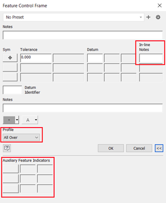
Additional identifiers were added to the Feature Control Frame style dialog to comply with ISO 5458, ISO 14405-1:2016, and ISO 1101 standards.
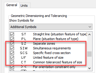
For more information see Style and Standard Editor - Feature Control Frame Style Reference.
