
- In the Modeling, Rigging, and Animation menu sets:
This topic covers the options in the Proximity Wrap window. For information on using the Proximity Wrap deformer, see Create a Proximity Wrap Deformer.
Basic tab
- Wrap Mode
- Select a method for the drivers to influence the geometry. Individual drivers use this mode when they are set to
Global.
Mode Behavior Surface Moves everything while considering surface normals. Use this mode when Offset mode fails. This mode requires more time to process as it must calculate surface normals. This setting is the default. Offset Applies the amount of vertices moved by the driver to the target vertices, according to the weighted influences. It ignores surface orientation so it may create artifacts when severe rotations are involved. But when that is not the case, Offset is an efficient way to apply driver deformations to the target. Snap Snaps the geometry to the driver and therefore behaves like some aspects of the ShrinkWrap deformer. It is also useful for debugging as it clearly depicts which parts of a driver are bound by the target. Rigid Uses driver geometry to calculate influences, and only uses the transformation of the driver to deform the target. In this way, it behaves similar to a skinCluster deformer. Cluster Note: The Cluster wrap option is available only in the Attribute Editor version of these options. To use Cluster, click the Attribute Editor ProxWrap tab and use the Wrap Mode menu there.Uses the driver Matrix inputs to transform vertices. - Max Drivers
- Use this field to set a limit on the number of drivers that influence a particular target vertex. When set to 1, each vertex uses the driver with the most influence. This may have less than ideal results, but when you combine them with post deformers, such as
Delta Mush deformer, you can find a balance between speed and quality. Typically,
Max Drivers is set to 3 or 4.
Note: If you use smoothInfluence with a non-zero value, each vertex can still end up with more driver influences than is specified here.
- Falloff Scale
- Scales the falloff distance of all drivers. It is a multiplier of the FalloffStart and FalloffEnd of each driver.
- Smooth Influences
- Once the driver influence is calculated from each vertex, you can smooth these influences by distributing them among their neighbors. The higher this value is set, the more the influences are spread and averaged.
- Smooth Normals
- Only active when Surface wrap mode is used.
- Instead of using direct surface normal, this setting runs a filter beforehand that smooths abrupt changes. Use this setting to generate softer-looking results.
Advanced tab
Specifies the placement of the deformer node in the deformable object’s history.
- Deformation order
- When you use one or more deformers to deform an object, the final effect of the deformations can vary based on the order the deformations occur. Select the deformation order to get the effect you want:
Order Effect Default Before Forces the deformer node ahead of the selected node in the chain even if a new geometry shape has to be created in order to do so. After Forces the deformer node to follow the selected node in the chain even if a new geometry shape has to be created in order to do so. Split Branches off a new chain in the dependency graph instead of inserting/appending the deformer into/onto an existing chain. Parallel Inserts the deformer in a parallel chain to any existing deformers in the history of the object. - Exclusive
- Specifies whether the deformer set is in a partition. Sets in a partition can have no overlapping members. If on, the Partition Name field becomes active. Default is off.
- Partition Name
-
Lists any existing partitions, and a default selection deformPartition. Click to edit the deformPartition field to specify the name of a new partition.
- Partition Name
-
Specifies the name of a new partition that will include the deformer set. The suggested partition name is deformPartition, which will be created if it does not already exist. Typically, you might put all your exclusive deformer sets in the partition named deformPartition. However, you can create as many partitions as you like, and name them whatever you want. Only available if Exclusive is on.
Attribute Editor
You can find additional controls for the Proximity Wrap deformer in the Attribute Editor Proximity Wrap tab.
- Proximity Wrap Attributes
- Many of these settings are defined in the Proximity Wrap Basic tab, above.
-
- Soft Normalization
-
Normally, the influences of all drivers on a particular vertex will be normalized. When Soft Normalization is turned on, normalization only occurs on vertices that have a total influences above 1.0. For example vertices with influences that amount to less than 1 are not normalized, and therefore only receive a partial effect of the proximity wrap deformer, which makes it act like envelope weights.
The most common use is to use the driver distance falloff as an envelope weight.
- Dropoff Rate Scale
-

- Use this option to control the inverse distance weight from the driver when using Proximity Wrap to perform skin binding. See Bind Skin Options to switch the Deformer Node from Skin Cluster to Proximity Wrap.
- Span Samples
- Set a number of samples per span to be used for higher accuracy (NURBs surface drivers only).
-
- Manage Drivers
-

- Opens the
Manage Drivers menu, where you can assign geometry as drivers.
Add Selected as Driver Connects the selected primitive to the deformer and becomes the driver of the deformation. Remove Selected as Driver Disconnects the selected primitive from the deformer so it is no longer driving the deformation. Edit New Driver Defaults Opens the the Proximity Wrap Drivers window, where you can configure the driver default settings. -
Note: Use the Pin Tab
 option to lock the Proximity Wrap tab in the
Attribute Editor, so you can select geometry without the tab switching.
option to lock the Proximity Wrap tab in the
Attribute Editor, so you can select geometry without the tab switching.
- Falloff Ramp
- Define the Shape of the driver's global falloff curve. Click the > arrow to rollout the falloff curve into a larger window where you can adjust the falloff.
-
- Selected Position
- The ramp value position on normalized 0-1 scale.
- Selected Value
- Ramp value at the sibling position.
- Interpolation
- Ramp Interpolation controls the way the intermediate values are calculated.
None No interpolation is done; different colors show up as different bands in the final texture. Linear Values are interpolated linearly in RGB color space. Smooth Values are interpolated along a bell curve, so that each color on the ramp dominates the region around it, then blends quickly to the next color. Spline Values are interpolated with a spline curve, taking neighboring indices into account for greater smoothness.
- Bind Tags
-
Use Bind Tags to fix unexpected vertex assignments
- If unexpected results occur on your deformed mesh, activate the Bind Tags option. In the animation above, a tearing effect in the deformed geometry is caused by the deformer misassigning vertices to random driver vertices on the tagged geometry. This is caused when default Component tags create conflicts with the position of the driver vertices.
- The Bind Tags filter lets you sort for the Component Tags with operators (see Component Tag expressions for more information about the operators you can use to filter).
-
Note: Component Tags are included with some primitives by default. If you don't want them applied, go into the primitive Tab (for example, Cube1) in the Attribute Editor and turn off the Component Tag Create option.
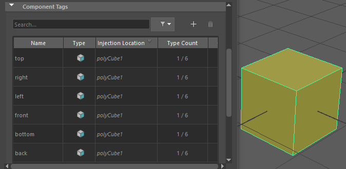
The default Component Tags of polyCube1.
- Driver Attributes
- Set the following driver attributes to deform your geometry.
-
- Cur Driver
- The deforming and/or transforming driver geometry. The deformation and/or transformation of this geometry is applied to the destination geometry (or, the geometry that is to be deformed). When this driver is set to Rigid Wrap mode, only the matrix of this geometry is used.
- Org Driver
- The bind geometry of the driver. This setting is used to calculate the proximity of the target geometry and what the influence the driver will have on the target geometry.
- Strength
- Adjusts the relative influence of the driver. It is a multiplier used to increase or reduce the influence of one driver relative to others that affect the same vertices.
- Wrap Mode
- Specifies the wrap mode of this driver. The global method by which drivers influence the geometry. Individual drivers will use this mode when they are set to Global. See Wrap Mode, in the Basics tab, above for description.
- Override Smooth Normals
- Activate this option if you want the driver to overrides the Smooth Normals value.
- Smooth Normals
- Set a number of smoothing iterations for the surface normals of the driver.
Note: This only applies to mesh drivers.
- Override Span Samples
- When active, the driver overrides the Span Samples value, below.
- Span Samples
- Set a number of samples per span to be used for higher accuracy (NURBs surface drivers only).
- Use Transform as Deformation
-

- Turn on this option if you want the driver to take the implied Transformation from other deformers into account. If you deactivate
Use Transform as Deformation, it will not take transformation from deformers.
Note: To use the implied transformation of other deformers, you can also connect the deformer World Matrix attribute to the Proximity Wrap Driver Cluster Matrix attribute in the Node Editor.Note: See Global Scaling with Proximity Wrap deformers for an example.
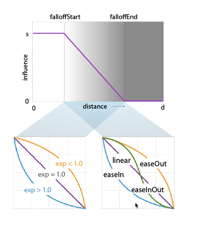
- Falloff Start
- The distance from the driver at which the influence begins to decline.
- Falloff End
- The distance from the driver at which the influence completely subsides.
- Override Falloff Ramp
- Activate for the driver to override the falloff ramp value.
- Falloff Exp
- Controls how much the influence changes within the falloff range (between FalloffStart and FalloffEnd). A Falloff exponent of 1.0 does not change the falloff shape. A value above 1.0 will further reduce the smaller influences, while values below 1.0 boost the smaller influences.
- Driver Falloff Ramp
- The Falloff Curve Lets you specify the shape of the falloff curve so you can moderate the way the deformation effect decreases. There are four preset shapes: EaseInOut, EaseIn, EaseOut and Linear.
-
- Selected Position
- Position of ramp value on normalized 0-1 scale
- Selected Value
- Ramp value at the sibling position.
- Interpolation
- Controls the way the intermediate values are calculated. Choose from:
Value Action None No interpolation; different colors appear as different bands in the final texture. Linear Values interpolated linearly in RGB color space. Smooth Values interpolated along a bell curve, so that each color on the ramp dominates the region around it, then blends quickly to the next color. Spline Values interpolated with a spline curve, taking neighboring indices into account for greater smoothness.