Objects
- NURBS Primitives
- Options in this menu let you create various geometric primitive shapes using NURBS surfaces or curves. You can create the primitives at the origin or, depending on the primitive options you have set, wherever you click your mouse in the scene view (Interactive Creation). Most of the options are shared between primitive types.
Select Create > NURBS Primitives > (object type) >
 to set the
NURBS Primitives Options.
to set the
NURBS Primitives Options.
- Polygon Primitives
- Options in this menu create a polygon-based geometric primitive at the origin or, depending on the primitive options you have set, wherever you click in the scene view (Interactive Creation). You can then move, scale, rotate, and reshape the new object using the standard tools and polygon menu items.
Note: When the view is set to High Quality Rendering mode, primitives created using the Interactive Creation option do not appear shaded until the primitive creation steps are complete.
See also Create polygon primitives.
The creation settings for many polygon types share some settings like Divisions, Axis, and Create UVs. See also Common settings for polygon primitives.
Select Create > Polygon Primitives > (object type) >
to set the
Polygon Primitives Options.
- Volume Primitives
- This menu lets you create various volume primitives that you can use in conjunction with lights and fog to create atmospheric volume effects. See Volume Primitives Options for more information.
- Lights
-
Options in this menu allow you create various lights. Select Create > Lights > <light type >

Light types: A. Ambient, B. Directional, C. Point, D. Spot, E. Area, and F. Volume
to view the settings specific to each light type:
- Ambient Light, an indirect light that comes from everywhere (A). See Ambient Light options.
- Directional Light, a light that comes from one direction (B). See Directional Light options.
- Point Light, a uniform light that emits from a single invisible point (C). See Point Lights options.
- Spot Light, a directional light, simulating a spotlight (D). See Spot Light options.
- Area Light, a rectangular light that simulates light from a window. (E.) See Area Light Options.
- Volume Light, a light with a source shape you can set (F). See Volume Light Options.
- Cameras
- Options in this menu allow you to create various cameras, such as a basic camera, or a stereo camera. Select
Create > Cameras > Camera
to set the
Create Camera options.
- Camera
- Creates a one-node camera, which is a basic camera.
For more information on the types of cameras, see Maya camera types.
- Camera and Aim
-
Creates a two-node camera, which is a basic camera plus an aim-vector control for aiming the camera at a specified “look at” point.
- Camera, Aim, and Up
-
Creates a three-node camera, which is a basic camera with the aim-vector control plus an up-vector control for rotating the camera.
- Stereo Camera
-
Creates a default stereo camera.
If you have created and registered a custom rig in your scene, your custom rig also appears in this menu. See Create a custom rig and Custom Stereo Rig Editor for more information.
- Multi Stereo Rig
-
Creates a default multi-camera rig for stereo cameras.
If you have created a custom multi-camera rig in your scene, your custom multi-camera rig also appears in this menu. See Create a multi-camera rig and Multi-Camera Rig Tool for more information.
- Curve Tools
-
Select from the following:
- CV Curve Tool
-
Lets you draw a NURBS curve by placing control vertices (CV).
Select CV Curve Tool >
to set the
CV Curve Tool Options.
- EP Curve Tool
- Lets you draw a NURBS curve by placing edit points.
Select EP Curve Tool >
to set the
EP Curve Tool Options.
- Bezier Curve Tool
- Lets you draw a freehand Bezier curve by clicking in the scene to create anchors. You can also click-drag to create anchors and tangents.
Select Bezier Curve Tool >
to set the
Bezier Curve Tool Options.
- Pencil Curve Tool
- Lets you draw a freehand NURBS curve. Select
Pencil Curve Tool >
to set the Pencil Curve Settings.
Choosing the Curve Degree: 1 Linear option creates jagged curves known as polylines.
See also Components of NURBS curves, Draw curves, Create > EP Curve Tool, and Create > CV Curve Tool.
- Three Point Circular Arc, Two Point Circular Arc
- Lets you create arcs by specifying points and then using a manipulator.
- Circular Arc Degree — 1 Linear creates jagged curves.
- Sections — Sets the number of curve segments of the arc.
Select Three Point Circular Arc or Two Point Circular Arc >
to set the options:
See also Create arcs.
- Type
- Adds a polygon mesh to the scene in the shape of styled text and connects it to a type node.
See also Type Tool.
- Sweep Mesh
-
Use Sweep Mesh to create a polygon mesh from a curve along the length of the curve path, then use SweepMeshCreator to customize the profile shape and size as well as alignment, and subdivisions.
Note:- Sweep Mesh is a plug-in, and must be activated in the Plug-in Manager.
- You must first have a curve created and selected before running Sweep Mesh.
- SVG
- Adds a polygon mesh to the scene in the shape of a default SVG object.
See also SVG Tool.
- Bifrost Graph
-
Adds a Bifrost graph to the scene for creating procedural effects. See Bifrost Extension for Maya.
Construction Aids
- Construction Plane
- Creates a construction plane to which you can snap construction tools.
- Pole Axis — Sets the orientation of the construction plane. The default is an
XY plane.

- Size — Sets the size of the plane in grid units.
Options in the Construction Plane are:
See also Create basic objects and Snap to a live surface.
- Pole Axis — Sets the orientation of the construction plane. The default is an
XY plane.
- Free Image Plane
-
A free image plane is an image plane that is not attached to the camera; one that you can select and transform in your scene. Select this option to create a free image plane.
A free image plane adjusts its size to match the image resolution ratio when you load a new image. See Editing and aligning free image planes for more information.
For more information on image plane attributes, see Image plane attributes.
Note:Rendering of free image planes is currently not supported by the Maya software renderer.
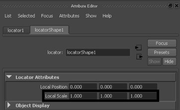
- Locator
- Creates a locator object in the scene. A locator is a small icon like an x-y-z axis that marks a point in space. They are useful as a user interface for characters; for example, you can parent joints to the locator so moving the locator pushes and pulls the joint.
An attribute on the locator shape node allows you to change the locator’s local scale; that is, you can change the size of the locator (without affecting any objects that are parented or constrained to the locator).
- Annotation
- Creates a text label with an arrow pointing to the selected object.
Deleting annotations does not remove the corresponding locator node from the scene. To delete the locator node, do one of the following:
- After deleting the annotation node, select the locator node and delete it.
- Select the annotation and press the pick walk up hotkey (default is up arrow key). The locator node will be selected and deleting it will also delete the annotation node.
- Selecting File > Optimize Scene Size. (See also Optimize Scene Size Options and Annotate or document objects.)
- Measure Tools
- The
Distance Tool,
Parameter Tool, and
Arc Length Tool tools create measurement objects that let you measure and annotate objects in the scene. As you move the points of the annotations, the listed measurements automatically update.
See also Measure the distance between two points and Show parameter or arc-length values on a curve or surface.
Scene Management
- Universal Scene Description (USD)
-
Use the option in this menu to create a USD stage. See Create a USD stage.
- Stage with New Layer: Creates an empty stage.
- Stage From File: Creates a USD stage from a file.
- Scene Assembly
- Use the options in this menu to create assembly reference and definition nodes.
- Assembly Definition — Creates an assemblyDefinition node. The Add Locator representation option is on by default. It adds a locator representation to the new assembly definition.
- Assembly Reference — Creates an assemblyReference node.
- Empty Group
- Creates an empty group node in the scene hierarchy.
See also Transforming objects, Scene hierarchy, and Group objects together.
- Sets
- The Set and Partition options let you create sets and partitions. Sets are loose groupings of objects used for various purposes. Partitions are groupings of sets that ensure the sets do not share members. See also Create and edit sets and Keep a collection of sets from having overlapping membership. The Quick Select Set submenu creates a new quick select set from the current selection. See also Save and reuse a selection.
- Asset
-
- Create Asset — Creates an asset with no associated transform. As a result, this asset does not appear in the DAG hierarchy and you cannot transform it in the scene. You can parent nodes external to the asset to it, but you must use parent anchors or child anchors to do so.
Select Create Asset >
to set
Create Advanced Assets Options.
- Create Asset with Transform — Creates an asset and automatically places any currently selected nodes into it. A transform node is also associated with the asset, allowing you to manipulate the asset node in the scene and DAG hierarchy as though it were a group node. If you parent other nodes to the asset, they are automatically placed inside the asset.
Select Create Asset with Transform >
to set
Create Asset with Transform Options.
- Create Asset — Creates an asset with no associated transform. As a result, this asset does not appear in the DAG hierarchy and you cannot transform it in the scene. You can parent nodes external to the asset to it, but you must use parent anchors or child anchors to do so.