- In the
Modelling and
Rigging menu sets: Deform >(Create)
Wire >

- In the
Animation menu set: Anim Deform > Open Full Deform Menu >(Create)
Wire >
To create a wire deformer with the Wire Tool, see Create Wire Deformers. The characteristics of the wire deformer you create depend on the Wire Tool’s tool settings. By default, the Wire Tool is set to create a wire deformer without holders.
See also Wire deformer and Paint wire deformer weights.
Wire Settings
- Holders
-
If on, the wire deformer is created with a holder. If off, the wire deformer is created without a holder. Holders are curves that you can use to limit the deformation region. Default is off.
- Envelope
-
Specifies the deformation scale factor. Use the slider to select a value between 0.0000 and 2.0000. A value of 0 specifies no deformation effect. Default is 1.0000.
- Crossing Effect
-
Specifies the amplitude of the deformation effect where two of the deformer’s influence wires cross. Use the slider to select values from 0.0000 to 2.0000. Default is 0.0000, which specifies a smooth, not additive, effect.
- Local Influence
-
Specifies the localization of the deformation effect of two or more influence wires. Use the slider to select values from 0.0000 to 2.0000. Default is 0.0000.
- Dropoff Distance
-
Specifies the range of influence of each influence wire. Use the slider to select values from 0.0000 to 10.0000. Default is 1.0000.
Deformation Order
Specifies the placement of the deformer node in the deformable object’s history. Placement selections include: Default, Before, After, Split, or Parallel.
- Default
-
Places the deformer immediately before the current final shape node.
- Before
-
Places the deformer immediately before the current final shape node. Default and Before typically provide the same placement.
- After
-
Places the deformer as the output of the current final shape node, and creates a new final shape node.
- Split
-
Splits the input deformation history into two separate deformation chains, providing two final shapes originating from the same deformable object.
- Parallel
-
Creates a final shape that blends the object’s current input history in parallel with the new deformer.
- Exclusive
-
Specifies whether the deformer set will be in a partition. If a deformer set is in a partition, the points in the set cannot be in any other set. The result is that only the deformer you are about to create can influence the points. If on, the Exclusive Partition and Existing Partitions options become available. By default, Exclusive is off.
- Exclusive Partition
-
Specifies the name of the partition. The default name is deformPartition. Only available if Exclusive is on.
- Existing Partitions
-
Specifies an existing partition. The default existing partition is characterPartition. Only available if Exclusive is on.
Attribute Editor

You can find additional controls for the Wire deformer in the Attribute Editor Wire tab.
- Bind to Original Geometry
- Lets you specify a separate mesh as the binding geometry for the wire deformer's deformation. This is useful when a mesh has already been deformed (for example, by a cluster deformer), but you want the wire to bind to its pre-deformed shape. (See Original geometry for an explanation of the Original Geometry attribute.)
- In the example below, we've taken a polygon plane and applied a cluster deformer to it. Then, on top of that, we apply a wire deformer
Bind to Original Geometry: Off Bind to Original Geometry: On - Wire deformer samples new points on the cluster deformed plane (D).
- Results in a plane that follows the wire more closely, with vertices shifted on the surface to match the cluster.
- If you were to move the underlying cluster deformer left and right, the vertices would slide back and forth along the bulge's surface while roughly maintaining the same overall shape.
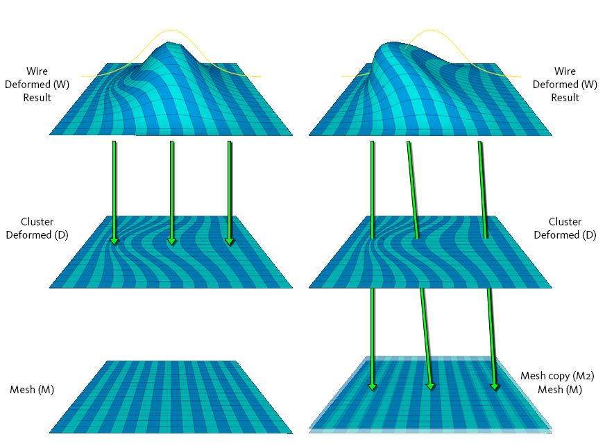
- Wire deformer bypasses the cluster deformed plane, and samples points directly from a provided mesh (M2).
- The provided mesh must be topologically identical to the deforming geometry. More often than not, it will be a copy of the pre-deformed base mesh (in this case, our plane).
- Results in a plane that deforms according to the vertices of the original mesh, so the shape follows the underlying cluster deformer in addition to the wire.
- If you were to move the underlying cluster deformer left and right, the bulge would follow.
Note: Turning this on also provides a boost to performance. So in cases where both results would be the same, you're better off turning this on. -
To connect a wire deformer to the base mesh
- (Optional) Duplicate the base mesh before any deformers are applied to it.
Note: You can bind the Wire node to any topologically identical mesh, but more often than not you'll want to use a copy of the base mesh.
- Apply your wire deformer to the object (along with any other deformers).
- In the Attribute Editor's Wire tab, turn on Bind to Original Geometry.
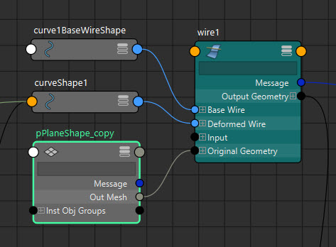
- Connect the base mesh duplicate's Out Mesh attribute to the Wire Deformer's
Original Geometry attribute, either via the
Node Editor,
Connection Editor, or by using the following MEL script:
connectAttr -f <object name>.outMesh <wire deformer name>.originalGeometry[0]
- (Optional) Duplicate the base mesh before any deformers are applied to it.