
- In the Animation or Rigging menu set:
Constrain >
UV Pin >

UV Pin derives its positions from simple UV coordinates, where Proximity pin derives its positions using a input matrices from transforms.
Connections
The Connections area lets you specify how pin locations on the target geometry are determined and how the output matrices are connected.- Pin locations
- Select where pin locations are derived from:
- Components: derived from location of the selected component
- Transforms: derived from the closest points on the surface to the selected transforms.
- Output
- Specifies how the output matrices are connected. You can see the connections in the
Node Editor.
Existing Transform Uses the selected transforms and connects them to the uvPin's output. (This is the default.) New Transform Creates new transforms at the specified UV coordinates and connects them to the nodes output. New Locator Creates new locators at the specified UV coordinates and connects them to the nodes output. Matrix Creates but does not connect any output plugs on the node, leaving the connection available.
Coordinate System
This section determines how the outputs are aligned to the coordinate system of the surface as derived from the surface normal and UV coordinates. Because the UV Pin node is procedural, you can continue to edit these settings in Attribute Editor after creation, including the ability to create extra Inputs and Outputs.
- Normal Axis
- Specifies what axis of the coordinate system of the outputs should align with the surface normal. Cannot be the same as Tangent axis.
- Tangent Axis
- Specifies what axis of the coordinate system of the outputs to align with the surface tangent. Cannot be the same as Normal axis.
- UV Set Name
- If you have multiple UV sets in the scene, select the set you want to use.
- Normalize Isoparms
-
Note: This option applies to NURBs only.
- Because coordinate values for NURBs may be parameterized differently, activate this setting to use absolute values.
- Relative space mode
-
 Use the menu to set your node evaluation space: World, Local, or Custom. Setting a different relative space
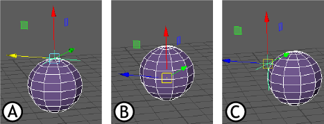
Relative space modes using UVpin and a Locator: A. World B. Local C. Custom
See World space, object space, and local space for descriptions of these spaces.Space Function World (Default) Uses the center of the scene as the origin.
Local Uses the geometry space for evaluation.
Custom Use an external matrix as the space for evaluation.
Attribute Editor options
The Attribute Editor UV Pin tab contains extra settings that are not covered in the Connections and Coordinate System sections.
- Manage Pins
-

-
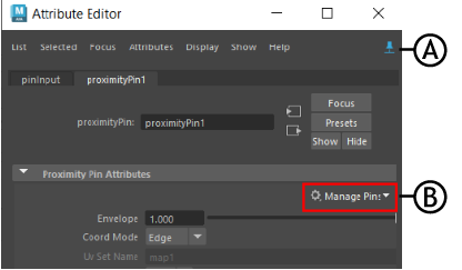
Attribute Editor: A. Pin Tab, B. Manage Pins menu
- Use this menu to manage operations you can apply to pin nodes. Choose from the following actions:
Select Geometry Selects the geometry affected by the UV pin. Replace Geometry with Selected Switches the pinned geometry with another selected geometry. Create Pins from Transforms Creates a new PinOutput node. To create pins from Transforms, select a transform node (locator/geometry/group, and so on). The Pin node outputs a pin value, connecting it to the node (depending on the Pin default setting). Create Pins from Components Create a new PinOutput node. To create Pins from Components, first switch the Pin default output value in the uvPin Options output menu so that the output is not "Existing transform". Then the Pin node outputs a pin value, and connects it to the node, depending on the Pin default setting. if you set the pin default to Existing transform, a warning appears informing you that you use Existing transform as an output when creating Pins from Components. and to change the Output type using the Edit Pin Defaults menu. Edit Pin Defaults Opens the UV Pin window, where you can set new values for the default pins: Existing Transform, New Transform, New Locator, or Matrix. Note: It is recommended to use the Attribute Editor Pin Tab while using this menu to keep the current attribute tab displayed when the selection changes.
- Normal Override
- Set Normal Override to Rail to let you connect the UV Pin constraint to Rail Curve geometry.