This example demonstrates how to create two texture nodes and blend them together.
It demonstrates how to:
- blend the textures using a Float node
- blend the textures by painting your vertices
- multiply your texture so that it repeats itself and produces a different effect
Creating a ShaderFX shader
 -click the object in your scene and select Assign New Material, then select Shaderfx Shader from the Assign New Material window.
- Click Open ShaderFX in the ShaderfxShader Attribute Editor to open the ShaderFX editor window.
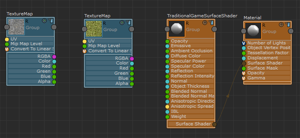
Three nodes are created automatically: Color, TraditionalGameSurfaceShader and Material. You can disconnect the Color node; it is not needed for the following workflow.
Creating two textures and blending them using the Float node
- Select Hw Shader Nodes > Textures > Texture Map to create a texture.
- In the Texture Map Attribute Editor, click the browse button beside MyTexture/Path and connect the first texture file. In this example, a concrete texture is used.
- Repeat steps 1 and 2 for the second texture. In this example, a grass texture is used.
Textures courtesy of www.cgtextures.com.
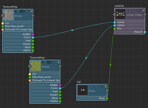
- Select Hw Shader Nodes > Math > Linear Interpolate Mix to create a Linear Interpolate Mix node to combine the two textures.
- Select Hw Shader Nodes > Values > Float to create a Float node.
- Connect the Color attribute of the first Texture Map to the first Value attribute of Linear Interpolate Mix.
- Connect the Color attribute of the second Texture Map to the second Value attribute of Linear Interpolate Mix.
- Connect the float attribute of the Float node to the Mix attribute of Linear Interpolate Mix. The Float node enables you to control the amount that each texture contributes to the blended result. For example, if set at 0.2, the resulting texture is dominated by the concrete texture. If set at 0.8, the resulting texture is dominated by the grass texture. If set at 0.5, it is an equal mix of the two.
- To see a swatch of the results, click the Render Swatch icon
 on top of the Linear Interpolate node.
- Connect the Result attribute of the Linear Interpolate Mix to the Diffuse Color attribute of the TraditionalGameSurfaceShader node. You can now visualize your shader in Viewport 2.0.

Blending the textures using the Vertex Color node
- Select Hw Shader Nodes > Inputs Common > Vertex Color.
Instead of using the Float node, you will use the vertex color to blend the textures.
- Disconnect the Float node from Linear Interpolate and connect the Red attribute of Vertex Color to the Mix attribute of Linear Interpolate Mix. This way, you use the Red channel to blend your textures.

- Before painting, select your plane. In the polyPlane node, increase the Subdivisons Width and Subdivisions Height to, for example, 20. This adds more vertices to your plane to increase definition for painting.
- Select Mesh Display > Apply Color >
 , and change the default vertex Color to black. This sets your default vertex color to black.
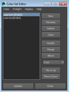
 - Select Mesh Display > Color Set Editor to open the Color Set Editor and check the name of the color set that has been created.
- Select the Vertex Color node in the ShaderFX editor and enter, in the Vertex / Color Set Name field, the name of the color set.

- If you have multiple color sets, make sure to select, in the Color Set Editor, the set that you want to paint on before painting.
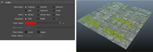
- With the plane selected, select Mesh Display > Paint Vertex Color Tool > .
You will now paint some of your vertices red. The vertices that are painted red will display your grass texture.
- In the Paint Vertex Color Tool settings, change your Color value to red.
- Paint on your plane. The vertices that you paint as red take on the grass texture values. You have now blended your textures by painting your vertices.
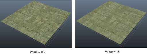
Multiplying your texture to repeat it in a tile pattern to create a different, more dense effect
- Select Hw Shader Nodes > Inputs Common > UV Set to create a UV Set node.
- Select Hw Shader Nodes > Math > Multiply to create a Multiply node.
- Select Hw Shader Nodes > Values > Float to create a Float node.
- Connect the UV attribute of the UV Set node to the Value attribute of Multiply.
- Connect the float attribute of the Float node to the other Value attribute of Multiply.
- Connect the Result attribute of the Multiply node to the UV attribute of the Texture Map (for which you want to repeat its pattern).

- Select the Float node, and change its Value in the Attribute Editor. Set it to a higher value so that the pattern repeats more often and is more dense, and a lower value so that the pattern does not repeat as often. You can preview the resulting pattern by clicking the Render Swatch icon of the Texture Map node.