The GLSL shading language specification does not contain a description that allows you to connect various shader fragments and their associated UI into a single effect file like it is possible with CgFX or HLSL.
Therefore, a wrapper file format is available that allows you to specify GLSL fragments for the various shading stages: to handle light and texture binding, and to determine how parameters are displayed in the Attribute Editor. This file format, .ogsfx, is described below.
To write a custom GLSL shader, save it as a .ogsfx file. See the WaterSimulation.ogsfx effects file in the ..\presets\GLSL\examples folder of the Maya installation for an example of how to write a GLSL shader.
This example demonstrates:
-
Texturing
-
Transparency
-
How to create UI in the Maya Attribute Editor
-
How to apply Maya lights to the shader
- How to perform hardware selection on displaced components
- How to draw displaced components
To visualize this example, create a cube and increase its Subdivisions Width and Subdvisions Depth to 100 via the polyCube node Attribute Editor. Press 6 for shaded and textured display mode.
Assign a GLSL shader to the cube and navigate to the WaterSimulation.ogsfx effects file. See Create and visualize a GLSL shader for more information.
The example shader creates an animated wave that can react to one Maya light in your scene. It is connected to a height and normal map and can display transparency.
For more information on the semantics and annotations used in this shader example, see Semantics and annotations supported by the dx11Shader and glslShader plug-ins in Viewport 2.0 and Shader semantics supported by Viewport 2.0.
To specify texture files
To define a file texture, follow this example:
uniform texture2D gHeightMap  <
    //Specify the texture file to be loaded by default
    string ResourceName = "SeaHeightMap.jpg";

    //Specify the type of texture
    string ResourceType = "2D";
    //Name of field in Attribute Editor
    string UIName = "Sea Height Map";

    int mipmaplevels = 0;
>;
uniform sampler2D gHeightMapSamp = sampler_state
{
    texture = <gHeightMap>;
};
Sampling is done on gHeightMapSamp, and the file texture is loaded in gHeightMap. The sampler_state allows the association of an external texture to a sampler.
The ResourceName annotation allows you to automatically connect and load the specified texture file when the shader is loaded. For example, in this case, the SeaHeightMap.jpg file is connected. Otherwise, the user must create a file node and connect it to the attribute.
In this case, the SeaHeightMap.jpg file is in the same directory as the WaterSimulation.ogsfx file. If the texture file is in a different directory, you must specify its full path.
To create an attribute in the Maya Attribute Editor
Uniforms automatically display in the Maya Attribute Editor with their variable name. To give your uniform a user-friendly name, use the UIName annotation.
For example:
uniform texture2D gHeightMap  <
...
...
  string UIName = "Sea Height Map";
...
>;
Sea Height Map appears as an attribute in the GLSLShader node Attribute Editor instead of gHeightMap.
If you do not want a uniform to display in the Attribute Editor, use the following annotation:
string UIWidget = "None";
To add a technique
A technique can contain one or more passes, where each pass defines a certain way of rendering an object. If you have more than one vertex shader and/or more than one geometry shader and/or pixel shader, you can specify which shader is to be used for each technique/pass.
In this example, technique Main contains one pass that specifies that the PS_Wave pixel shader should be used. When you select Main as your technique in the GLSLShader node Attribute Editor, the waves are rendered in the viewport.
Similarly, technique NormalView contains one pass that specifies that the PS_Normal pixel shader should be used. When you select NormalView in the Attribute Editor, the normal map of the waves are shown in the viewport.
The technique NormalView_Selection includes 7 passes, and different vertex, geometry and pixel shaders are used for each pass. This technique demonstrates hardware selection. For more information, see To select and draw displaced components below.
To display transparency
Use the Transparency technique annotation when you specify your technique so that your object can display transparency.
The following allows the object to appear transparent when the Main Technique is selected in the GLSLShader Attribute Editor.
technique Main
<
//tell Maya to support transparency for this technique
string Transparency = "Transparent";
>
To assign lights in the scene to your shader
The Light 0 Group section of the example effects file demonstrates how to assign one light in your scene to your GLSL shader, and how the light parameters should affect the shader.
To include more than one light in your shader calculations, create additional Light 1, Light 2 (and so forth) sections in your effects shader. You will also need to program how the lights interact with each other.
There are 3 ways to add lights to your shader. You can:
- auto-bind any light in your scene to your shader by selecting the Automatic Bind option from the Light Binding section of the Attribute Editor
- manually select and bind a specific light in your scene to your shader by selecting it from the Light Binding section
- adjust your light settings via the GLSLShader Attribute Editor. You must select the Use Shader Settings option and first select Enable Light 0 before the settings take effect.
If you select either of the first two options, you cannot change the light parameters in the GLSLShader Attribute Editor after binding a light. Instead, you must make changes from the light Attribute Editor.
To see the effect of your scene lights, select Lighting > Use All Lights in the Maya viewport panel menu.
To disable consolidation
Set the technique annotation handlesConsolidatedGeometry to false to disable the Consolidate World feature on the geometry to which the GLSL shader is applied.
string handlesConsolidatedGeometry = "false";
This annotation is useful if your technique draws displacement, the calculations of which involve the object-space co-ordinates of an object, such as use of the World transformation matrix. Because Consolidate World moves vertices of multiple objects into a new shared object-space, your plug-in shader may render incorrectly as a result. In this case, you may want to disable Consolidate World.
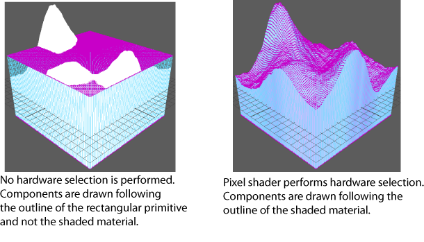
To select and draw displaced components
The technique NormalView_Selection demonstrates how to perform hardware selection on displaced components, and to render non-material items (such as wireframe and selected edges/vertices) at their displaced positions.
Hardware selection allows you to select tessellated geometry. In addition, wireframe and components draw with the same outline as the shaded material in the viewport. This technique has 7 different passes.
Before defining the techniques, the #include directive is used to load four shaders as follows. The #include directive allows you to share the same GLSL fragments between different applications, and maintain separate shader code files instead of having to combine them all into one .ogsfx file.
GS_FatLine.ogsfh: This is a geometry shader that converts a line to a rectangle, and therefore allow render lines to be drawn bigger (for example, red pre-selection highlighting edges are drawn larger than dormant edges).
GS_FatPoint.ogsfh: This is a geometry shader that converts a point to a quad, and therefore allow render points to be drawn bigger (for example, vertices are rendered as a square instead of a single pixel).
PS_SolidColor.ogsfh: This is a pixel shader that draws with a solid color.
PS_HWSelection.ogsfh: This is a pixel shader that renders the components during hardware selection, where each component is rendered in a different solid color that is calculated using the object or component ID.
The first 4 passes are used for drawing in the viewport; therefore the PS_Normal and PS_SolidColor pixel shaders are used.
- Pass pNormal: renders the textured material
-
Pass pNonMaterialItems: renders components such as wireframe and vertices. Components are rendered with a solid color, such as blue for edges of dormant objects and light green for edges of active objects.
-
Pass pNonMaterialItemsFatLine: renders lines using the GS_FatLine geometry shader.
-
Pass pNonMaterialItemsFatPoint: renders points using the GS_Point geometry shader.
The last 3 are used to render components during hardware selection, and therefore the PS_HWSelection pixel shader is used. The PS_SolidColor pixel shader is not used, as these passes are not used to draw in the viewport.
A primitive id (such as vertex id) is used to produce a color to identify the object that is picked. An offscreen buffer is used to store these computed colors so that Maya knows what is picked by the mouse.
-
Pass pNonMaterialItemsSelection: used for selection of components such as wireframe and vertices.
-
Pass pNonMaterialItemsSelectionFatLine: used for selection of fat lines
-
Pass pNonMaterialItemsSelectionFatPoint: used for selection of fat points.
Technique and pass annotations
The overridesNonMaterialItems technique annotation specifies that this technique can be used to render non-material items such as the wireframe and components like edges or vertices.
string overridesNonMaterialItems = "true";
Pass annotations are used to tell the plug-in which pass to use for which render items.
For example:
pass pNonMaterialItemsFatLine
<
// This pass will be used to render non material items as fat lines
string drawContext = "nonMaterialItemsPass";
string primitiveFilter = "fatLine";
>
Therefore, if a render item is categorized as a non-material item, and the primitive type is categorized as fat line, then the pNonMaterialItemsFatLine pass is used.
For information about these pass annotations, see Supported pass annotations.
For more information about OverrideNonMaterialItems, see MRenderItem::RenderItemType in the Maya Developer Help.