
Note: The
Show Manipulator Tool, used in this task, appears only if
Construction History is on.
To extrude polygon faces or edges
- Select the faces or edges you want to extrude.
Note: In the Modeling preferences, ensure that Keep faces together is on, so the edges of adjacent faces stay connected after the extrude operation.
- Do one of the following:
- Activate the Move, Rotate, or Scale Tool and Shift + drag the manipulator (also known as smart extruding).
- Select Edit Mesh > Extrude.
- Click
 in the
Modeling Toolkit.
in the
Modeling Toolkit.
- Press Ctrl + E
An extrude node is created. If you did not use the quick extrusion method, then the Show Manipulator Tool and In-View Editor will also appear.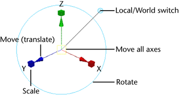 Note: Vertices will extrude along their vertex normals, creating additional faces for each face that shares those vertices.
 - Do one of the following:
- Use the manipulator to control the direction and distance of the extrusion
- Adjust the attributes in the
In-View Editor
Tip:
 With the
In-View Editor displayed and active, select an attribute in the marking menu (Ctrl + Shift + Right-click) to make your selection the active attribute in the
In-View Editor. You can cycle through the list of attributes using Ctrl + Tab (cycles from the bottom of the list to the top) or Ctrl + Shift + Tab (cycles from the top of the list to the bottom).
With the
In-View Editor displayed and active, select an attribute in the marking menu (Ctrl + Shift + Right-click) to make your selection the active attribute in the
In-View Editor. You can cycle through the list of attributes using Ctrl + Tab (cycles from the bottom of the list to the top) or Ctrl + Shift + Tab (cycles from the top of the list to the bottom).
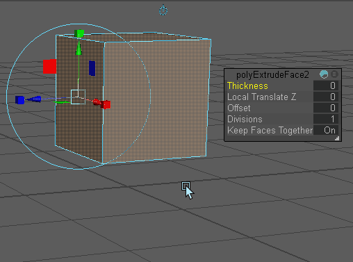
Tip: You can set the precision for the Thickness, Offset, and Divisions attributes by selecting Edit > Settings > Change Precision in the Channel Box. The In-View Editor uses the same precision settings as the Channel Box. - (Optional) Extruding edges can make your mesh non-manifold. Use Mesh > Cleanup to fix non-manifold geometry.