Select from the following constraint types:
Point
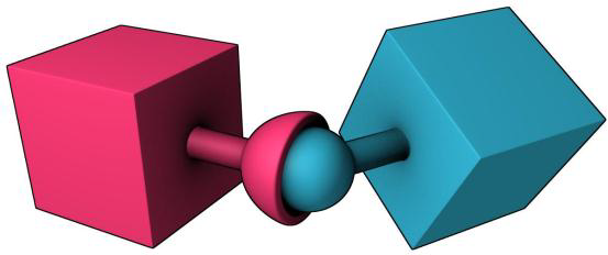
The Point constraint (called a point-to-point constraint in the Bullet Physics library) limits the translation so that pivot points between the two rigid bodies match in world space. You can use the Point constraint to create effects, such as a chain-link, or to pin objects together.

The Point constraint supports the following attributes:
- Angular Dampening
Hinge
The Hinge constraint restricts the translation and two additional angular degrees of freedom, so the body can only rotate around one axis. The hinge axis is defined by the Z axis of the constraint. This constraint is useful for representing doors or wheels rotating around an axis. The user can specify limits and motor settings for the hinge.

The Hinge constraint supports the following attributes:
- Angular Limit Softness
- Angular Limit Bias
- Angular Limit Relaxation
- Angular Constraint Min Z
- Angular Constraint Max Z
- Angular Motor Enabled (turns the Z axis motor on and off.)
- Angular Motor Target Speed (specifies the Z axis target velocity.)
- Angular Motor Max Force (specifies the maximum motor impulse that can be applied to the Z axis in a single simulation step.)
Slider
The Slider constraint allows rigid bodies to rotate around one axis and translate along the same axis. The slide axis is defined by the Z axis of the constraint.

The Slider constraint supports the following attributes:
- Linear Damping
- Linear Softness
- Linear Restitution
- Linear Limit Bias
- Linear Limit Softness
- Linear Limit Relaxation
- Linear Constraint Min X
- Linear Constraint Max X
- Linear Motor Enabled (turns the motor on the X axis on and off.)
- Linear Motor Target Speed (specifies the target velocity for the motor. Only the X field is used.)
- Linear Motor Max Force (specifies the maximum motor impulse. Only the X field is used.)
- Angular Damping
- Angular Softness
- Angular Restitution
- Angular Limit Softness
- Angular Limit Bias
- Angular Limit Relaxation
- Angular Constraint Min X
- Angular Constraint Max X
- Angular Motor Enabled (turns the motor on the X axis on and off.)
- Angular Motor Target Speed (uses only the X value.)
- Angular Motor Max Force (uses only the X value.)
Cone-Twist
The Cone-Twist constraint supports the following attributes:
- Angular Damping
- Angular Limit Softness
- Angular Limit Bias
- Angular Limit Relaxation
- Angular Constraint Max X (specifies the twist span angle in degrees.)
- Angular Constraint Max Y(specifies the swing span 2 angle in degrees.)
- Angular Constraint Max Z (specifies the swing span 1 angle in degrees.)
- Angular Motor Enabled (turns the motor on the X axis on and off.)
- Angular Motor Max Force X
Six Degrees-of-Freedom
The Six Degrees-Of-Freedom (SixDOF) constraint can emulate a variety of standard constraints if each of the six Degrees of Freedom (DOF) is configured. The first 3 DOFs axis are linear axis, which represent the translation of rigid bodies, while the latter 3 DOFs axis represent the angular motion. Each axis can be locked, free, or limited. By default, all axes are unlocked.

The Six Degrees-Of-Freedom constraint supports the following attributes:
- Linear Damping
- Linear Softness
- Linear Restitution
- Linear Constraint
- Linear Constraint Min
- Linear Constraint Max
- Linear Motor Enabled
- Linear Motor Target Speed
- Linear Motor Max Force
- Angular Damping
- Angular Softness
- Angular Restitution
- Angular Constraint
- Angular Constraint Min
- Angular Constraint Max
- Angular Motor Enabled
- Angular Motor Target Speed
- Angular Motor Max Force
Spring Hinge
The Spring Hinge has three degrees-of-freedom. These include two rotational degrees-of-freedom around Z (Axis 1) and X (Axis 2), and one translational along Z (Axis 1) with a suspension spring. A use-case example of a Spring Hinge constraint is the steering wheel of a car, where one axis allows the wheel to be steered while the other axis allows the wheel to rotate. For this case, you need to rotate the spring hinge -90 in X to align Axis 1 with Y.
The Spring Hinge constraint has an anchor point for Axis 2, which is specified by the position of the constraint. Axis 1 is specified relative to body 1. This would be the steering axis if body 1 is the chassis. Axis 2 is specified relative to body 2 and is perpendicular to Axis 1 (along X). This would be the wheel axis if body 2 is the wheel. Axis 1 (along Z) can have springs as well as angular and linear limits, but Axis 2 (along X) is free. You cannot have springs and motors enabled at the same time. If you want to drive Axis 2, modify the X Torque Impulse of body 2.

The Spring Hinge constraint supports the following attributes:
- Linear Constraint
- Linear Constraint Min Z
- Linear Constraint Max Z
- Linear Spring Enabled
- Linear Spring Stiffness
- Linear Spring Dampening
- Angular Constraint
- Angular Constraint Min Z
- Angular Constraint Max Z
- Angular Spring Enabled
- Angular Spring Stiffness
- Angular Spring Dampening
Spring Six Degrees-Of-Freedom
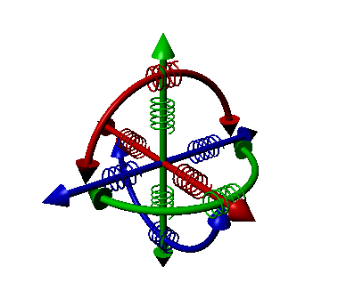
The Spring Six Degrees-Of-Freedom (SpringSixDOF) constraint is a variant of the Six Degrees-of-Freedom constraint that includes the addition of springs for each of the degrees of freedom. Springs and motors cannot be combined on this constraint.

The Spring Six Degrees-Of-Freedom constraint supports the following attributes:
- Linear Constraint
- Linear Constraint Min
- Linear Constraint Max
- Linear Spring Enabled
- Linear Spring Stiffness
- Linear Spring Dampening
- Angular Constraint
- Angular Constraint Min
- Angular Constraint Max
- Angular Spring Enabled
- Angular Spring Stiffness
- Angular Spring Dampening