Use these options to control the behavior of your Volume Axis field.
- Magnitude
-
Specifies the strength of the volume axis field.
- Attenuation
-
Sets how much the strength of the field diminishes from the central axis of the volume axis field.
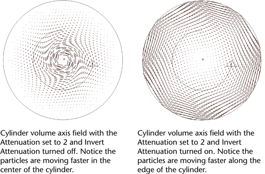
If you set Attenuation to 1, the strength of the field diminishes in a linear manner from full strength at the central axis to zero strength at the edge of the volume axis field. Values greater than 1 make the strength of the field diminish to zero in an exponential manner—the greater the value, the more rapidly the strength decreases.
A value of 0 makes the strength remain constant from the central axis of the volume axis field to its edge (see also Invert Attenuation).
Distance
- Use Max Distance
-
Turn this on to apply the value set in Max Distance.
- Max Distance
-
Sets the maximum distance at which the field has an effect. You must also turn on Use Max Distance for Max Distance to take effect.
Note: The Max Distance and Attenuation attributes operate in a special way for the Volume Axis field. For all volume axis shapes except sphere, distance (for both the Max Distance and Attenuation attributes) is defined as the distance from the volume’s central axis to the point.For cylinder, cone, and cube, the central axis is the positive Y axis. For torus, the central axis is the ring in the center of the solid part of the torus. The sphere volume is an exception— it uses the center point, not the center axis (it works like the other fields).
This special definition of distance applies only to the Volume Axis field. It does not apply to other fields even when they are using volumes.
- Falloff Curve
-
Available when Use Max Distance is checked.
When using a field to exert force, sometimes the object receiving the force may have trouble settling down after the force is exerted. Use this curve to modulate the force. For example, scale the field’s force so that it smoothly drops off to zero at the boundary defined by the Max Distance value.
The curve is defined within the normalized distance; in other words, 0 to 1, where 0 corresponds to the field's center and 1 corresponds to the Max Distance value. The value from the curve is a scaling factor to be applied to the force.
Note: Fallout Curve is only available as an attribute after you create the field. It is not available an a field creation option.
Volume Control Attributes
- Volume Shape
-
Specifies the closed volume that defines the area in which the volume axis field affects particles and rigid bodies. You can choose from five volume shapes: cube, sphere, cylinder, cone, and torus.
The implicit shape of the volume axis field is displayed on the screen. You can move, rotate, scale, or shear the field.
Note:You can’t deform the volume or use an arbitrary volume.
- Volume Offset X, Y, Z
-
Offsets the volume axis field from the actual location of the field.
- Volume Sweep
-
Defines the extent of the rotation for all volume shapes except cube. This can be a value from 0 to 360 degrees.
- Section Radius
-
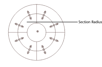
Defines the thickness of the solid portion of a torus volume shape.

Volume Speed Attributes
- Invert Attenuation
-
When you turn on Invert Attenuation and you have Attenuation set to a value greater than 0, the strength of the volume axis field is strongest at the edge of the volume and diminishes to 0 at the central axis of the volume axis field (see also Attenuation.

- Away From Center
-
Specifies the speed at which particles move away from the center point of cube or sphere volumes. You can use this attribute to create explosive effects.
- Away From Axis
-
Specifies the speed at which particles move away from the central axis of cylinder, cone, or torus volumes. For torus, the central axis is the ring in the center of the solid part of the torus.
- Along Axis
-
Specifies the speed at which particles move along the central axis of all volumes.
- Around Axis
-
Specifies the speed at which particles move around the central axis of all volumes. When used in conjunction with a cylinder volume shape, this attribute can create swirling gaseous effects.
- Directional Speed
-
Adds speed in the direction specified by the Direction XYZ attributes of all volumes.
- Direction X, Y, Z
-
Moves particles in the directions specified by the X, Y, and Z axes.
Tip:When working with volumes, it’s sometimes useful to set the Conserve attribute to 0 in the particle shape. This keeps the particles within the volume. Particles will not exit the volume unless other forces act on them to make them do so. Also, see Keep particles inside the volume.
- Turbulence
-
The intensity of a force simulating a turbulent wind that evolves over time.
- Turbulence Speed
-
The rate of change of the turbulence over time. The turbulence loops seamlessly every 1.0/Turbulence Speed seconds. To animate this rate attach a new time node to the time input and animate the time value on the time node.
- Turbulence Frequency X, Y, Z
-
Controls how many repeats of the turbulence function fit inside the bounding volume of the emitter. Low values create a very smooth turbulence.
- Turbulence Offset X, Y, Z
-
Use this option to translate the turbulence within the volume. Animating it can simulate blowing turbulent wind.
- Detail Turbulence
-
The relative intensity of a second higher frequency turbulence. Both the speed and the frequency on this second turbulence are higher than the primary turbulence. When the Detail Turbulence is non-zero the simulation may run a bit slower, due to the computation of a second turbulence.
Volume Curve attributes
Use these attributes as additional controls for volume curves. They appear in the volumeAxisField Attribute Editor after you create a Volume Curve.
Volume Trapping
When using a volume shape field, you can set volume trapping properties to keep objects from exiting the volume field. Trapping properties work with all volume shapes and volume curves.
- Trap Inside
-
Applies a force to the volume field that keeps objects inside the volume. When Trap Inside is set to a value greater than 0, Trap Radius and Trapped Ends become available.
- Trap Radius
-
Sets the radius (as a local space distance) from the volume boundary within which the Trap Inside force is applied.
- Trap Ends
-
Creates ends on volume cylinders, cones, and curves that trap objects inside the volume or curve.
Axial Magnitude
Creates a ramp which scales field Magnitude along the volume axis.
- Selected Position
-
This value indicates the position of the field Magnitude on the ramp. For a volume curve, the left position on ramp represents the field Magnitude at the base of the curve, while the right position on the curve represents the field Magnitude at the tip of the curve. For volume cylinders, the left position on the ramp represents the field Magnitude at the cylinder's bottom, while the right position on the ramp represents the field Magnitude at the cylinder's top.
- Selected Value
-
This value indicates field Magnitude at the Selected Position.
Interpolation
Controls the way field Magnitude blends between positions on the ramp. The default setting is Linear.
- None
-
The Axial Magnitude curve is flat between points.
- Linear
-
The Magnitude values are interpolated with a linear curve.
- Smooth
-
The Magnitude values are interpolated along a bell curve, so that each value on the ramp dominates the region around it, then blends quickly to the next Magnitude value.
- Spline
-
The values are interpolated with a spline curve, taking neighboring indices into account for greater smoothness.
Curve Radius
Creates a ramp which scales the Section Radius of a volume axis curve. The Curve Radius ramp is only applicable to volume field curves.
- Selected Position
-
This value indicates the position of the Section Radius value. The left position on ramp represents the Section Radius at the base of the curve, while the right position on the curve represents the Section Radius at the tip of the curve.
- Selected Value
-
This value indicates Section Radius value at the Selected Position.
Interpolation
Controls the way field Section Radius blends between positions on the ramp. The default setting is Linear.
- None
-
The Curve Radius curve is flat between points.
- Linear
-
The volume curve radius values are interpolated with a linear curve.
- Smooth
-
The radius values are interpolated along a bell curve, so that each value on the ramp dominates the region around it, then blends quickly to the next radius value.
- Spline
-
The values are interpolated with a spline curve, taking neighboring indices into account for greater smoothness.