Controls, options, and settings explained
The
context view holds most of the controls to work with supports. Additionally, the
 Settings hold a number of switches for less often used properties.
Jump to:
Context view tabs
The support editor uses five tabs in the context view to display its options, Analysis, Edit, List, Support scripts, and Process simulation.
 The arrangement of some elements has been straightened, and some visuals-related options have been removed and moved to the main menu's
View category instead.
The arrangement of some elements has been straightened, and some visuals-related options have been removed and moved to the main menu's
View category instead.
| Tab | Primer | Additional Notes |
|---|---|---|
|
Analysis |
Cluster detection controls how the downskins, made up of triangle clusters, are detected for viewing and for manual support generation. Also provides switches that affect on-screen display. For example, you may wish to hide the platform surface, or have supports displayed partly transparent. Note: Transparency requires OpenGL 3.3 capability, otherwise these settings are disabled.
|
|
|
Mark cluster manually holds the settings for manually selecting triangles to be supportable clusters |
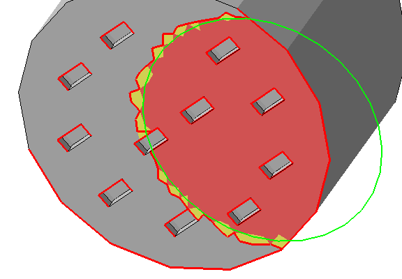 The edge threshold makes marking large areas with many small perforations much easier. Note: Manual marking and automatic detection cannot be combined. Also, the critical and non-critical angle for manual marking is fixed at 90°.
|
|
|
|
|
|
|
View displays a volume estimation for support structures currently present |
|
|
|
Edit |
Edit the generation settings for the currently selected support entity here, either by adjusting values directly or applying a set. |
Use Sets to manage custom values for supports. Sets are also looked up whenever you place supports manually. |
|
List |
Any available support elements are listed here, grouped by the clusters they belong to.
|
|
|
Support Scripts |
Support scripts are at the heart of Netfabb's support generation. They consist of support actions with already defined values. These can be saved and loaded for later use, even exported and imported. |
The example scripts that come with Netfabb cannot be edited. However, you can copy them and edit the copies.
|
|
Process simulation |
Contains visibility and visualization settings for the display of simulation results. |
These print simulation results are generated by using a metal powderbed machine workspace based on material and toolpath selection and sending the generated solution to Autodesk® Simulation Utility for Netfabb® (included in the Ultimate subscription) or Autodesk® Netfabb® Local Simulation as included in the separate product Autodesk® Netfabb® Local Simulation. This tab also includes the controls to optimize lattice support, including a histogram display for bar support elements that compose the optimized support structures. |
 Mark cluster manually
Settings
These are located at
Settings > Settings > Support Module.
| Colors |
Set the colors used for things like the platform, mesh, supports, anchors, and down-oriented edges |
| Number of decimal digits |
Adjust this to have the required number of decimal places displayed. |
| Zoom animation duration |
To help with recognizing the orientation of a part after a switch of perspective, the transition to the new perspective is animated. Use this to affect the speed at which the animation runs. Expects the time in milliseconds. |
| Show cutplanes |
When using the clipping planes, or cutting planes, this switch toggles visible, semi-transparent planes at the cuts. When off, only the contours along the clip or cut are highlighted. |
| Zoom orientation |
When switching through support entities in the List tab while Zoom to selection is active, this perspective is used when focusing on the respective support entity. |
| Mouse action for bar support |
For the command
|
|
Ask on deletion of all support |
Toggles whether to ask for confirmation upon choosing to delete any and all existing supports. |
| Laser diameter for volume calculation |
For calculating the amount of material rendered for non-solid supports, this diameter is used as the width of a single-pass toolpath. |
| Export as part attachment |
Set this to No when you do not want to create supports as attachment but rather as separate part. Some older applications and formats need this as they do not recognize dedicated support structures. For example, attached support is dropped when exporting meshes to STL instead of the modern 3MF. Note: You can always convert support structures regardless how you generated them using the
Manage Support command in the
Home toolbar, but keep in mind that attaching a mesh that was parametric previously does not restore the parameters how it was generated, so you cannot edit them in the support editor.
Caution: The meshes so generated can be, and often are, unsuitable for printing as regular parts where support-specific toolpathing would otherwise accept the technically flawed mesh just fine. Make sure that either you process the support meshes appropriately yourself or that they are inherently treated as supports by your workflow anyway.
|
| Respect part environment |
When set to No, the support editor ignores any part other than the one you are currently working on in the support editor even when it would intersect with projected supports of the current part. This also includes no-build zones. 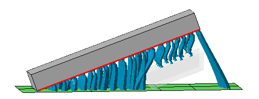 Two separate blocks in the build room. One is being worked on in the support editor, the other one (displayed with transparency) is acknowledged by the editor. Note how only a section of the other part is taken into account even though it is actually a full copy of the first (not shown). This is done for performance reasons but may lead to unexpected results like the bar supports to the platform on the far right. |
 Environment size
|
Sets the extra space around a part to be checked for other parts. Increase this if you often work with widespread parts closely nested against each other. |
| Use voxelgrid for walls |
Supports near walls can interfere with the same walls. When using the voxel grid approach, the wall detection is improved but the calculation cost increases. |
| Voxelgrid size, Voxelgrid height |
The size of the voxels determines accuracy of wall detection and avoidance but incurs proportional computation costs. |
| Show Apply behavior dialog |
When applying support from the support editor, you are asked with a dialog whether to keep or terminate the support editor entry in the project tree. The dialog contains a checkbox to choose to always use this dialog. After unchecking the box, your last choice is remembered and the dialog no longer appears. With this option, you get the dialog to appear again. |
|
Remove old support before script execution
|
Typically, a support script is there to generate all required support at once, invalidating and possibly even negatively interfering with existing supports. As such, the default is to delete any existing support before running the script. Setting this switch to No disables the deletion. |
 Support projection height,
Constant height
Support projection height,
Constant height
|
In some additive processes, parts do not require supports to reach all the way to the platform and be anchored there, they just need a flat base to stand on. This setting effectively simulates a fixed distance of the part to the platform for supporting purposes regardless at what Z height in the buildroom the part actually sits. Switch Support projection height from On to platform to Constant height to enable this function, and use the parameter Constant height to specify this simulated fixed distance. |
 Create new bar