The Degrees of Freedom section of the Constraints form allows you to select the translational and rotational degrees of freedom of the nodes associated with the selected entities that are to be constrained.
The constraint symbols will be visible only after applying them to a Subcase.
There are multiple buttons that, when clicked, automatically check the structural degrees of freedom to be constrained. For example, a Fixed constraint would check all boxes as shown in the figure below.
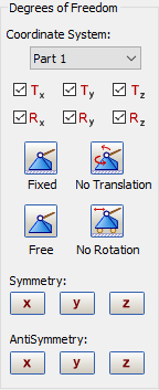
The Coordinate System pull-down menu allows you to apply a constraint in a custom coordinate system.
The example in the figure below illustrates its use.
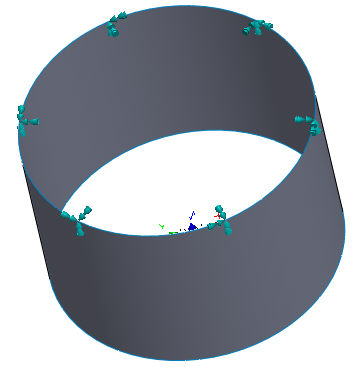
The constraint in this example is applied in the custom cylindrical coordinate system in the theta (θ) direction.
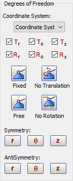
Notice that the degrees of freedom are renamed based on the coordinate system type, like
 ,
,
 and
and
 for radial, theta and z constraints respectively in a cylindrical coordinate system.
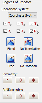
When a spherical coordinate system is assigned in the
Constraint dialog, the degrees of freedom
 ,
,
 and
and
 for radial, theta and phi (ϕ) constraints respectively, look as shown below.
A No Translation constraint in a rectangular coordinate system would make selections as follows:
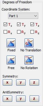
Symmetry constraints can be applied by using buttons under Symmetry, like X (Tx, Ry, Rz constrained) etc.
Antisymmetry constraints can be applied by using buttons under AntiSymmetry, like X (Ty, Tz, Rx constrained) etc.
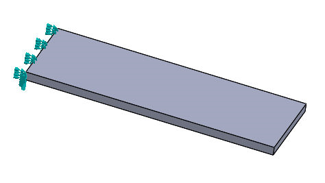
Fixed constraint on an edge
After adding the constraint, right-click on it and select Remove to remove it from the Subcase. This does not delete the constraint, only removes it from the FE Model tree section.
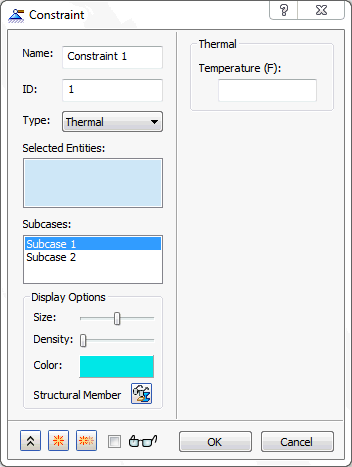
When the Type is Thermal, a fixed Temperature constraint can be applied to selected entities as shown in the figure below.
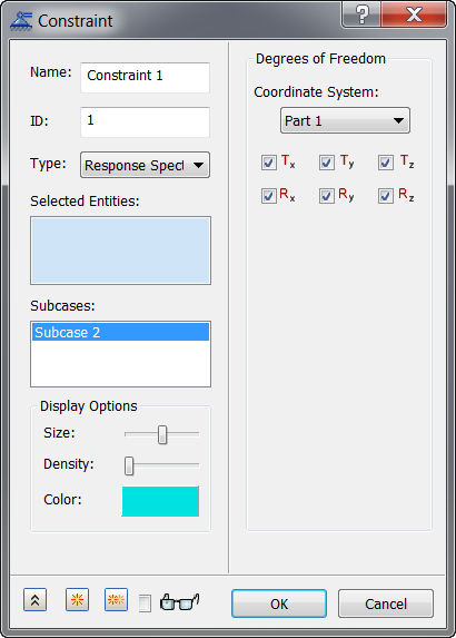
When the Type is Response Spectrum, constraints can be applied to selected entities. Each constraint represents a unique component in the Nastran SUPORT Bulk Data entry.
When the Type is Pin, constraints can be applied to cylindrical faces only. Apply surface pin constraints to cylindrical surfaces to prevent the surfaces from moving or deforming in combinations of radial, axial, or tangential directions.
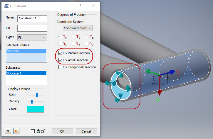
When the Type is Frictionless, constraints are intended to prevent surfaces from moving or deforming in the normal direction. These constraints can be applied to either parallel flat faces, or concentric cylindrical faces.