Six-Sided Solid Element Connection
Description: Defines the connections of a six-sided isoparametric solid element with eight to twenty grid points.
Format:

Example:

| Field | Definition | Type | Default |
|---|---|---|---|
| EID | Element identification number. | Integer > 0 | Required |
| PID | Property identification number of a PSOLID entry. | Integer > 0 | Required |
| Gi | Grid point identification numbers of connection points. | Integer ≥ 0 or blank, all unique | Required |
Remarks:
- Element identification numbers must be unique with respect to all other element identification numbers.
- Grid points G1 through G4 must be given in consecutive order about one quadrilateral face. Grid points G5 through G8 must be in order in the same direction around the opposite face with G5 opposite G1, G6 opposite G2, etc.
- Any or all of the edge points, G9 through G20, may be deleted. If the ID of any edge connection points is left blank or set to zero (as for G11 and G12 in the example), the element equations are modified to give the correct results for the reduced number of connections. Corner grid points cannot be deleted.
- Components of stress are output in the volume coordinate system. (See the VOLUME command in Section 3, Case Control.)
- The material coordinate system is defined on the PSOLID entry.
- The second continuation is optional.
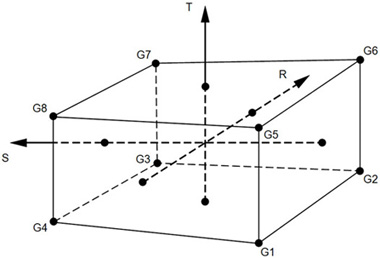
- The element coordinate system for the CHEXA element is defined in terms of the three vectors R, S, and T, which join the centroids of opposite faces.
- R vector joins the centroids of faces G4-G1-G5-G8 and G3-G2-G6-G7.
- S vector joins the centroids of faces G1-G2-G6-G5 and G4-G3-G7-G8.
- T vector joins the centroids of faces G1-G2-G3-G4 and G5-G6-G7-G8.
The origin of the coordinate system is located at the intersection of these vectors. The X, Y, and Z axes of the element coordinate system are chosen as close as possible to the R, S, and T vectors and point in the same general direction.
- It is recommended that the edge points be located within the middle third of the edge.
- By default, all of the twelve edges of the element are considered straight unless an edge node is specified using G9 through G20.

Figure 1. CHEXA Element Connection

Figure 2. CHEXA Element R, S, and T Vectors