Use the Pattern finishing page to create a toolpath using the projection of a pattern or toolpath onto the model. The pattern can contain any number of open or closed segments.
Drive curve determines which curve or set of curves will be used to create the cutting moves.
Use toolpath — Select to use a 3-axis toolpath as the drive curve. In effect, this axially offsets the toolpath up Z by the tool tip radius and then converts this toolpath to a pattern. Offsetting the toolpath by the tool tip radius converts the tool tip coordinates to tool centre coordinates. For a ball nosed tool the tip radius equals the tool radius. You can use this to convert an existing 3-axis toolpath into a multi-axis toolpath.
 Create pattern — Click to create a new empty pattern.
 Selected pattern — Select a pattern from the list. If no pattern is displayed, or
 is selected, then no pattern is selected. The list contains a list of all available patterns.
 Select picked pattern — Click to select a pattern by picking in the graphics window, rather than by name in the
Select pattern list.
Select picked pattern — Click to select a pattern by picking in the graphics window, rather than by name in the
Select pattern list.
Clicking
displays the
Pick Entity tab. Select a pattern in the graphics window to close the
Pick Entity tab and display the pattern in the
Selected Pattern field.
 Collect curves — Click to copy the selected curves into the pattern. This provides a fast, powerful means of extracting curve geometry from a surface model and copying it into the active pattern/boundary. For more information, see the
collecting curves example.
Collect curves — Click to copy the selected curves into the pattern. This provides a fast, powerful means of extracting curve geometry from a surface model and copying it into the active pattern/boundary. For more information, see the
collecting curves example.
- Automatic
— Drops the tool onto the part down the tool axis. This is the same as
Drop
when the tool axis is vertical.

If you have a different tool axis, you get a different result:
- Drop
— Drops the tool onto the part down the Z axis. This is the same as
Automatic
when the tool axis is vertical.
- Drive curve
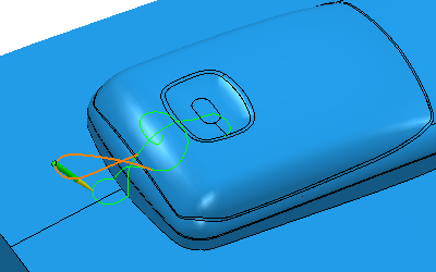
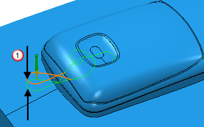
— The pattern is not dropped onto the model. The toolpath follows the pattern.

Looking at the simulated toolpath:

Axial offset — Enter the distance to offset the pattern along the tool axis. For the toolpath to be above the pattern enter a positive value. Zero depth is where the tool tip touches the pattern. This option is available only if you select a Base position of Drive curve. If you use a negative offset, so the pattern gouges (or engraves) the part, the result depends on the Gouge avoidance options selected.
 Axial offset
Tolerance — Enter a value to determine how accurately the toolpath follows the contours of the model.
Ordering — Enables you to reorder the pattern segments to reduce the link distances.
- Free Direction - reorders the segments, allowing them to be reversed.
- Fixed Direction - reorders the segments but does not allow them to be reversed.
- Pattern - keeps the order the same as the input pattern. No re-ordering takes place.
Thickness — Enter the amount of material to be left on the part. Click the
Thickness
 button to separate the
Thickness
box in to
Radial thickness
button to separate the
Thickness
box in to
Radial thickness
 Axial thickness
 . Use these to specify separate
Radial and
Axial thickness as independent values. Separate
Radial and
Axial thickness values are useful for orthogonal parts. You can use independent thickness on sloping walled parts, although it is more difficult to predict the results.
. Use these to specify separate
Radial and
Axial thickness as independent values. Separate
Radial and
Axial thickness values are useful for orthogonal parts. You can use independent thickness on sloping walled parts, although it is more difficult to predict the results.
Radial thickness — Enter the radial offset to the tool. When 2.5-axis or 3-axis machining, a positive value leaves material on vertical walls.
Axial thickness — Enter the offset to the tool, in the tool axis direction only. When 2.5-axis or 3-axis machining, a positive value leaves material on horizontal faces.

 Component thickness — Click to display the
Component thickness
dialog, which enables you to specify the thicknesses of the different surfaces.
Component thickness — Click to display the
Component thickness
dialog, which enables you to specify the thicknesses of the different surfaces.
 Set stepdown from tool — Click to automatically define the stepdown from the tool geometry.
Preview — Click to display the pattern used to create the toolpath.
Draw — Select to display the preview pattern.