Base AutoCAD Object
| Example: |
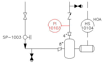 |
| Description: | An AutoCAD object or block (instead of an AutoCAD P&ID component) has been inserted in the drawing. Such blocks do not show up in reports or in the Data Manager, even though they may look like a P&ID component. |
| To Correct: |
|
Size Mismatch
| Example: |
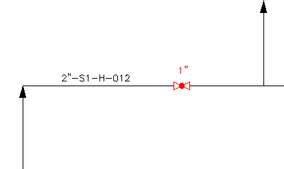 |
| Description: | The size of a line and its associated component do not match. This condition is usually caused by manual changes to the component properties. |
| To Correct: |
|
Spec Mismatch
| Example: |
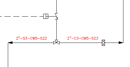 |
| Description: | The specification properties (details such as the component material) for lines and inline components do not match. This condition is usually caused by manual changes to the properties. |
| To Correct: |
|
Non-terminating Line
| Example: |
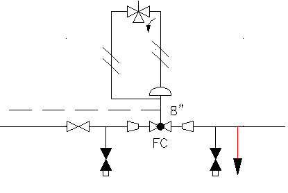 |
| Description: | Process lines do not terminate through a connection to an endline component, or do not end with an endline symbol signifying an air vent, water outline, drain, or other valid terminator. |
| To Correct: |
|
Unconnected Component
| Example: |
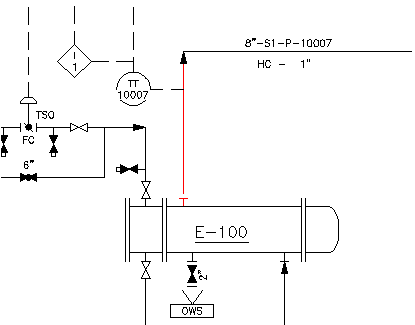 |
| Description: | No true connection exists for lines and their associated components, even though they appear to be connected. This error may result if a proper connection was never established, or if a component was dragged away from a line. |
| To Correct: |
|
Flow Direction Conflict
| Example: |
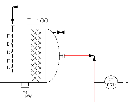 |
| Description: | The flow direction is incorrect for a line or component. |
| To Correct: |
|
Orphaned Annotation
| Example: |
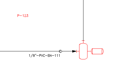 |
| Description: | An annotation tag has been moved away from the component with which it is associated. |
| To Correct: |
|
Unresolved Off-page Connectors
| Example: |
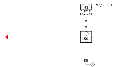 |
| Description: | Off-page connectors used to connect the current drawing with another drawing do not specify a valid project location. |
| To Correct: |
|