Note: This tab is available if you selected the Internal Engine method for calculating internal forces.

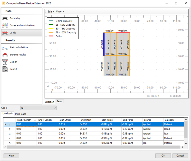
Use the Loads tab to review definitions of load cases from the Robot model.
- From the Case list, select a load category.
It displays load cases corresponding to the selected category on the Line loads or Point loads tab, depending on how a load case is defined.
Select All to display the full list of loads in the model.
- Select the Beam tab in the graphic viewer and review each load case and combination.
Each load case you select in the table is visualized in the graphic viewer.
Line load data
- Start / Length, End / Length
Relative location of load application.
- Start Offset, End Offset.
Location of load application.
- Start Force, End Force.
They specify load values at the start and end points of application.
- Source. Source of load:
- Applied: taken directly from Robot + self-weight
- Ponding: based on composite settings - ponding load
- Deck: based on composite settings - deck area factor
- Construction dead: based on composite settings - dead load
- Construction live: based on composite settings - live load
- Reaction: loads from upper members (loads of carried member).
- Category. Load categories according to the code:
- Construction dead
- Construction live
- Dead
- Live
- Material
- Roof
- Snow.
Point load data
- Offset / Length. Relative location of load application.
- Offset. Location of load application.
- Force. Load value at the point of application.
- Source. Source of load:
- Applied: taken directly from Robot + self-weight
- Ponding: based on composite settings - ponding load
- Deck: based on composite settings - deck area factor
- Construction dead: based on composite settings - dead load
- Construction live: based on composite settings - live load
- Reaction: loads from upper members (loads of carried member).
- Category. Load categories according to the code:
- Construction dead
- Construction live
- Dead
- Live
- Material
- Roof
- Snow.