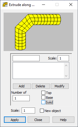
The option is used to create simple planar or solid-like elements by extruding predefined 2-dimensional objects along a specified polyline. The option is available using one of the following methods:
- Click Geometry menu > Objects > Extrude along Polyline.
- Click Along Polyline (first, a defined object must be selected) in the Objects: operations/modifications dialog.
- Click
 .
.

The Extrude along Polyline option functions in a way similar to the Extrusion option, because it is a composite of several operations of extruding an object based on the definition of a polyline.
To extrude a predefined 2-dimensional object along a specified polyline, you should define several parameters:
- broken line (polyline)
- Scale - specifies the scale coefficient for particular segments of a polyline (default value: 1, which means that scaling is not applied to the extruded object). If the scale value is larger than 1.0, the object is enlarged when extruded along a given segment of the polyline. If the scale value is smaller than 1.0, the object is reduced when extruded along a given segment of the polyline.
- Number of divisions - specifies the number of divisions to be carried out when an object is extruded.
- Top - the upper side of the object yielded by extrusion - is created, when this option is selected.
- Base - the lower side of the object yielded by extrusion - is created, when this option is selected.
- Solid - selecting this option causes a volumetric structure (solid) to be created during object extruding. The option is available for volumetric structures.
- Scale - specifies the general scale coefficient (default value: 1, which means that scaling is not applied to the extruded object). If the scale value is larger than 1.0, the object is enlarged. If the scale value is smaller than 1.0, the object is reduced. Note: If a value different from 1.0 is entered, the ratio of the base of the object to its top will equal the entered value for each segment of the polyline. In other words, the scale of the object is recalculated for each segment of the polyline.
- New object- when selected, the object extruded along a polyline receives a new number.
The polyline can be defined graphically (highlighting successive points of the polyline) or textually (by defining coordinates of successive points of the polyline). The successive points of the polyline are entered in the appropriate field in the Extrude along Polyline dialog. The points can be deleted or modified (define the new coordinates of the point and, optionally, the scale value; then, click Modify).
To extrude an object along a polyline:
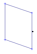
- Define a 2-dimensional object, such as, a rectangle (see the following image). Let us assume that the coordinates of its vertices are: (-2,0,-2), (2,0,-2), (2,0,2), (-2,0,2).

- Select the object.
- Open the Extrude along Polyline dialog.
- Define a polyline. Let us assume that its parameters are:
- (0,0,0) scale 1.0
- (0,10,0) scale 1.0
- (0,10,10) scale 2.0
- Define the remaining parameters of extrusion. Let us assume the following parameters for the rectangle and the polyline previously defined: Division number - 10, top and base options - inactive, the general scale - 1.0, and new object option - inactive.
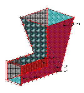
- Click Apply to extrude the predefined rectangle. The operation yields the object in the following image.
