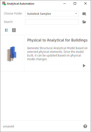
Automate the creation, element connection, and update of the analytical model using the physical model as context.
To use physical to analytical automation:
- In the Analyze tab
 Structural Analytical Model panel, click
 (Analytical Automation).
Using the physical model as context, generate the analytical elements and connect them. Once the analytical model is built, it can be updated based on physical model changes.
Input Data
Select Physical Elements
In the Revit model, select the physical elements for which you want to create or update the analytical representation.
- Structural columns (architectural columns are not supported).
- Walls
- Structural framing (including the ones that are part of beam systems or trusses).
- Floors
Foundations are not considered in this process.
All the other elements are kept in the selection but excluded from the analytical model creation and update process.
The supported elements of a group are considered.

Adjust Elements Using Connectivity Rules
- Create/Update the analytical element position, geometry and parameters.
- Connect the analytical elements.
To also connect the analytical elements after creation and update, the
2.1. Adjust analytical elements using connectivity rules option needs to be set to
 (True). The default value is True.
The connectivity rules adjust the analytical elements position starting from a mark.
- The nearest level -
3.1 Adjust analytical elements to nearest level is set to
 (True).
A tolerance that defines the nearest level is set using the 3.2. Tolerance of the distance to the nearest level parameter. E.g., set the tolerance value to 0,5.
Tip: This distance is set in the length units of the project. Fractional units can be set in their decimal form. -
The first group of elements considered in adjustment, when the nearest level option is disabled - Set 4.1The first group of elements considered in adjustment to Wall.
There are two other priorities in considering the adjustment order: - The second group of elements considered in adjustment - Set 4.2. Second group of elements considered in adjustment to Column.
- The third group of elements considered in adjustment - Set
4.3 .Third group of elements considered in adjustment to Beam.
To consider elements that need to be connected, set the tolerance for the distance between two end/corner nodes of the analyzed elements - 2.2. Tolerance of the distance between analytical elements. E.g., set the tolerance value to 0,35.Tip: This distance is set in the length units of the project. Fractional units can be set in their decimal form.
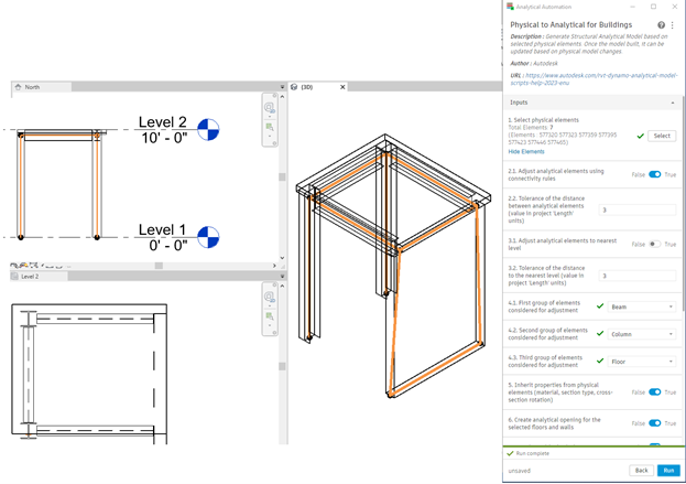
| Example 1: Adjust elements without considering the nearest level |
|---|
|
Note:
|
|
Reasoning:
|
 |
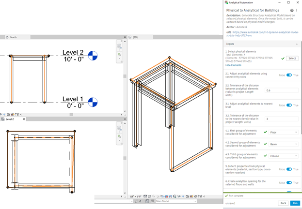
| Example 2: Adjust elements considering the nearest level as main reference |
|---|
|
Note:
|
|
Reasoning:
|
 |
| Example 3: Adjust elements considering a very small tolerance between analyzed nodes |
|---|
|
Note: The analytical panel was created on the floor contour. The analytical columns, analytical beams and the analytical wall positions are adjusted to the analytical panel surface, but these elements are connected on the area of the panel, not on its nodes.
|
|
Reasoning:
|
 |
Inherit Properties from the Physical Elements
On creation/update, you can choose if the analytical element parameters should match the values of the ones of their physical counterparts.
The option is enabled by default -
5. Inherit properties from physical elements (material, section type, cross-section rotation) is set to
 (True).
- Analytical member:
- Section type and family.
- Material.
- Cross-section rotation.
- Structural role.
- Analytical Panel:
- Thickness (structural layer thickness for the multiple layer elements).
- Material (structural layer material for the multiple layer elements).
- Structural role.
Create Analytical Opening
You may choose whether or not to create the analytical openings based on the physical ones.
The option is enabled by default -
6. Create analytical openings for the selected floors and walls is set to
 (True).
Associate with the Physical Counterpart
You may choose to associate the physical elements used as context and their analytical counterparts.
 (True).
Output
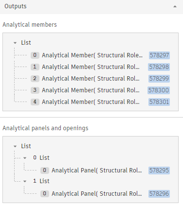
After creation or update all the analytical members are grouped in two lists: one for the members and the other one for panels and openings.
The list can help you identify elements and/or changes in the creation and update process:
