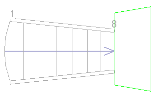
When creating a stair assembly, create a custom-shaped landing component by sketching the boundary.
Sketching a landing component allows you to create a custom-shaped landing. If you need to modify a landing component that was created automatically during stair creation to have an irregular shape, use the Convert to Sketch-Based tool to convert the component to a sketch-based component, and edit the sketch.
Important: When you create components by sketching, they do not have the automatic relationship to each other as when stair components are created with the common component tools. For example, if you sketch run and landing components, then change the run width, the landing shape will not change automatically. Sketched components must be updated manually.
To create a landing component by sketching
- Open a plan or 3D view.
- Enter stair assembly edit mode:
- To sketch a landing component for sketched runs, select a run, and on the Edit panel, click
 (Edit Stairs).
- To sketch a landing component for a new stair assembly, click Architecture tab
 Circulation panel
 (Stair).
- To sketch a landing component for sketched runs, select a run, and on the Edit panel, click
- Click Modify | Create Stair tab
 Components panel
 (Landing).
- In the Draw gallery, click
 (Create Sketch).
- On the Draw panel, click
 (Boundary).
- Sketch the landing boundary using the drawing tools. See
Sketching Elements.

- Optionally, you can draw a custom stair path to indicate the walk line. Click
 (Stair Path), and sketch the path.
Note: The stair path sketch is used to generate the annotation stair path. If you would like to change the way the stair path is represented, you can edit the stair path sketch.
 - Click
 (Finish Edit Mode) to exit sketch mode.