Connectors, attached to families, are used to connect the family to duct, piping, electrical, and other systems.
You can place connectors using one of the following methods:
-
Place on Face
This option (Edge loop centered=true) maintains its point at the center of the edge loop.
Note: This is the recommended method for placing a connector. -
Place on Work Plane
This option allows placement of the connector on a selected plane. For many cases, you can imitate the Place on Face option by specifying a plane and using dimensions to constrain the connector to the desired location. However, this method generally requires additional parameters and constraints to be used effectively.
Connector Orientation
Fittings (pipe and duct fittings) expect the instance origin of the family to be the intersection of the connectors. In most cases for fittings, there is a point on the fitting where all of the connectors (if extended into the fitting) will collide. Fittings expect this collision to be placed at the original intersection of the Center (Front / Back), Center (Left / Right), and Reference Level work planes. For this reason, it is good practice to pin these reference planes before beginning to build the family.
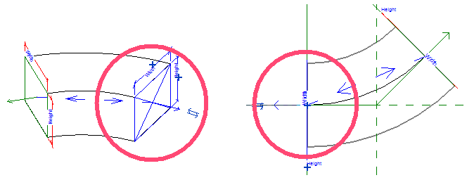
When you place fitting connectors, the primary connector must be placed on the face that is on the X-axis. Crosshairs display indicating that this is the primary connector. You can verify this by viewing the face in a floor plan view. Unexpected behavior can result if the primary connector is not properly placed relative to the other connectors, and if all connectors are not properly rotated and linked.

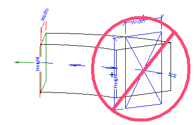
Connector rotation is a critical part of connector placement. The connector orientation determines the correct orientation of the objects that are automatically inserted on the part. Although this is not as important for round connectors, it is extremely important for rectangular connectors such as those on rectangular duct fittings. For rectangular connectors, the rectangular connector must be oriented so that the width is assigned to the face that is on the X and Y axes. The height is not on these axes. If rectangular connectors are not rotated properly, the rectangular duct fitting will be inserted improperly, creating an unexpected result. You may find it easier to rotate connectors in a 3D view, where the part geometry is clearly visible.

Connector arrows indicate the direction of a duct or pipe (extrusion) when it is being created to complete a connection. It does not indicate flow direction. In most instances, a connector arrow points outward away from the object to which the connector is associated. Otherwise, the duct or pipe when created will pass through the object geometry instead of away from it. You can modify the connector arrow direction by selecting the connector and clicking the flip arrows.
