Choose a reference view label from a list of existing names, or create an empty view that you can edit later.
- Open a plan or callout view.
- Click View tab
 Create panelElevation drop-down
 (Elevation).
 - On the Reference panel, select Reference Other View.
- Select a reference view from the drop-down list. (For a long list of view names, it can be helpful to enter keywords in the Search field to quickly locate the reference view name.) If there are no existing views to reference, you can select <New Drafting View> from the menu. This creates an empty drafting view that is added to the Project Browser under Drafting Views. The default name is Elevation of <level name>. You can edit this view as necessary and rename it.Note: If a view from the menu list is on a sheet, the detail number and sheet number display next to the view. For example, if you choose a drafting view, and it is on a sheet, its name displays as Drafting View: Drafting 1 (1/A101), where the values in the parentheses represent the detail number and sheet number.
- Place the cursor in the drawing area and click to place the reference elevation.
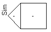
The reference elevation displays in the drawing area with the default reference label, as shown in the following image.
To change the label text, select the reference elevation symbol, and on the Properties palette, click
 (Edit Type). Edit the Reference Label type parameter and click OK.
 - Optionally, select the elevation symbol, and add check marks where you want to create additional reference elevations.
When you select a check box, the Select View to Reference dialog opens. Select the view to reference and click OK.
Note: To change the view referenced in the elevation after the reference is created, select the reference elevation symbol, and on the Reference panel, select a reference view name from the drop-down list.