You can place 3D beams using 3D lines, curves, and edges from geometry imported with CAD files.
This allows the engineer to model complex dimensional framing from the data of a 3D architectural drawing. This eliminates the need to recreate designs in Revit.
To place beams using imported drawings
- Import the CAD model. See Importing CAD Files.
- Open a 3D view in which to place the beams.
Tip: Change the visual style to Wireframe to view all lines of the model.
- Click Structure tab
 Structure panel
 (Beam).
- In the Type Selector, select a beam type.
- On the Properties palette, modify beam parameters.
- Click Modify | Place Beam tabDraw panel
 (Pick Lines).
- On the Options bar, select the following:
- the appropriate placement plane in which to place the beams. Endpoint z-direction offsets are calculated from this level.
- a structural usage
- 3D Snapping
- Move the cursor over the imported drawing. When you place the cursor over valid 3D lines, curves, and edge references, they will highlight.

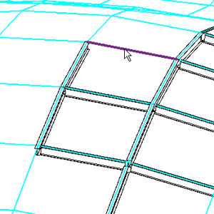
- Click valid lines, curves, and edges to place beams.
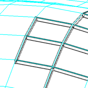
Beams sharing common endpoints are joined to one another and subject to join and cutback principles of behavior. See Geometry manipulation and cutback on framing elements.
Once placed, 3D beams are independent of the imported drawing. The drawing can be unlinked or removed from the Revit model without affecting the orientation of the placed beams.