In sketch mode, specify properties for parallel boundary lines to create a sloped surface.
You can use this method to create a sloped surface on the following types of elements:
- soffits
- floors
- structural floors
- ceilings
To create a sloped roof, see Roof Slope.
To slope a building pad, see Create a Sloped Surface Using a Slope Arrow.
To create a sloped surface
- If you are not already in sketch mode, select the element in a plan view, and click Modify | <Elements> tab
 Mode panel
 (Edit Boundary/Footprint/Sketch).
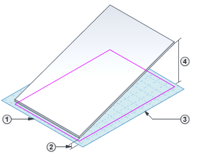
 - Select one boundary line, and, on the Properties palette:
- Select Defines Constant Height.
- Enter values for Level
 and Offset From Base
  .
.
- Select a parallel boundary line, and, using the same method, specify the properties for Level
 and Offset From Base
  .
. 
- On the ribbon, click
 (Finish Edit Mode).
To see the resulting sloped surface, open a 3D view or a section view.