Define Code Parameters
Learn how to create new type of member and how to assign it to the selected elements in the structure.
Continue working in your project or open the project Frame_3D_Results.rtd.
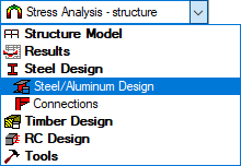
Note: The Tutorial files are located in C:\ProgramData\Autodesk\Examples\TutorialsIn the Standard toolbar, expand the Layouts drop-down menu and select Steel/Aluminum Design as shown below:
The layout is divided in three parts: View, Definitions, and Calculations dialogs.
Click Design > Steel Members Design - Options >
 (Code parameters).
The Member Type dialog opens.
Select Beam, and then click
 (New steel member type definition).
The Member Definition Parameters dialog opens.
Tip: Select the Member Type that is most similar to the new type that you want to create so that some of the basic properties are automatically applied.Type Beam_1 in the Member type text box.
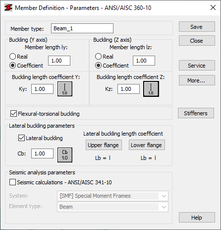
In the Buckling length coefficient Y group of options, click
 .
.The Buckling Diagrams dialog opens.
Click
 , and then click OK.
The buckling effects are removed from the calculations.
Repeat steps 6 and 7 for the Buckling length coefficient Z.
In the Lateral buckling parameters group, click
 .
.The Parameter Cb dialog opens.
Click
 , and then click OK.
Click Upper flange, then in the Lateral buckling length coefficients dialog, click
 (Intermediate bracings).
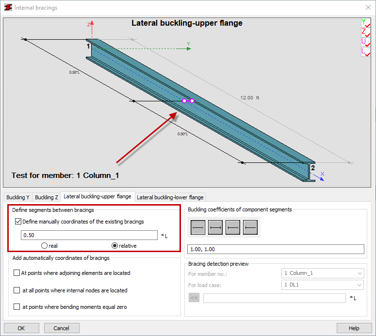
The Internal bracings dialog opens.
In the Define segments between bracings group of the Lateral buckling-upper flange tab select Define manually coordinates of the existing bracings, and then type 0.5.
The Bracing is displayed in violet on the view as shown below.
Go to the Lateral buckling-lower flange tab and repeat step 12 for the lower flange.
Click OK to close the Internal bracings dialog.
The information in the Member Definition dialog box should now look like the example shown below.
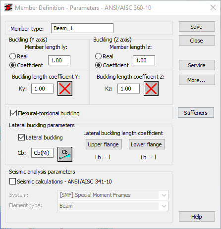
Click Save, and then click Close.
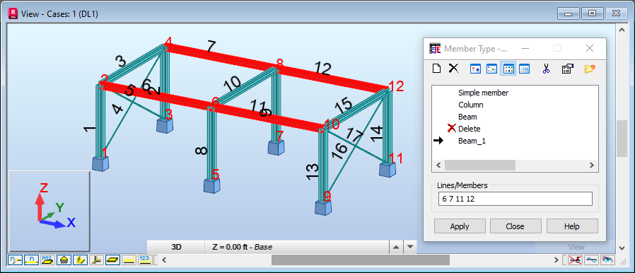
The new member type is now listed in the Member Type dialog.
Ensure that Beam_1 is selected in the Member Type dialog, and then type 6 7 11 12 in the Lines/Members field as shown below.
Alternatively, place the cursor in the Lines/Members field, then go to the drawing area, and hold the Ctrl key to select beams with numbers 6, 7, 11 and 12.
Click Apply, and then click Close.
Save the project as Frame_3D_New_Member.rtd.