Create the Flow Volume
There are two distinct fluid regions in this model. One is created automatically when the model is opened into Autodesk® CFD because it is fully enclosed by the casing, inlet fan, and baffle.
The other is not fully bounded, so we will have to use the Void Fill Geometry Tool to create the internal fluid volume. This is done by first creating a surface at the opening that causes the flow volume to be fully enclosed. We will then complete the creation of the internal volume.
Click Geometry Tools from the Setup tab.

On the Geometry Tools dialog, select the Void Fill tab.
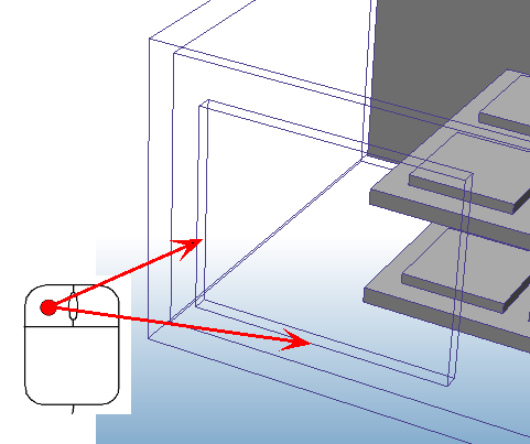
Select two edges on the outlet that share a vertex. If your model is shaded, right click on the model and select Outline for better visibility.

Click the Build Surface button
Click the Fill Void button to complete the volume.
The result is a volume that is bounded by the baffle and the outlet surface.
Close the Geometry Tools dialog.
For more about Void Fill Geometry tool.