Material Assignments: Air
To use Autodesk® CFD for simulating HVAC ventilation, we need to define both the structural elements and the internal air, even though we don't generally "build" air as a part of a CAD or BIM model. In this step, we'll define the big empty space that's inside the exhibition hall to be air.
Be default, we can't see the air part because it is blocked by the wall part.
1. To see the air, hide the wall by holding Ctrl and middle clicking on it:
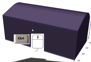 | 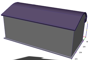 |
2. Select the air part by left clicking on it:
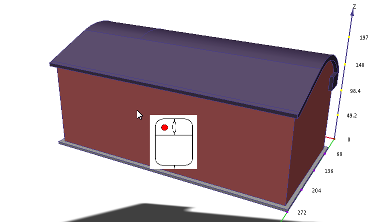
3. Click Edit from the Materials context panel:

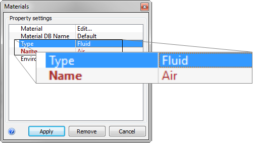
4. On the Materials quick edit dialog, verify the Type is Fluid, and the Name is Air.
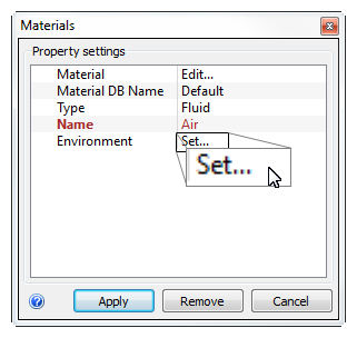
5. In the Environment row, click Set...
6. On the Material Environment dialog, click Variable
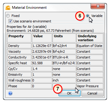
7. Click OK.
8. Click Apply on the Materials quick edit dialog.
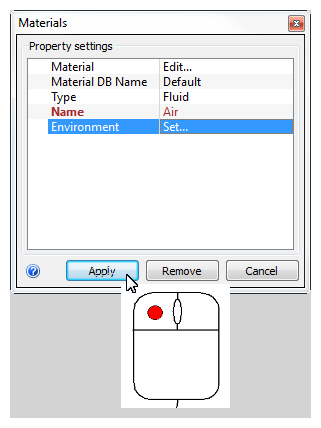
What it should look like...
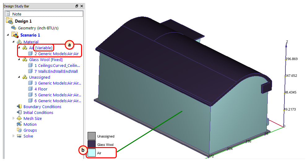
9. To verify that the air material is properly assigned, check the Design Study Bar and the part coloring:
- a. In the Design Study Bar, confirm the material setting on the Air part. (Be sure the word Variable follows the Air material name.)
- b. The air part should be colored blue to correspond to the Air color in the legend.
