Velocity Results
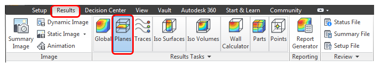
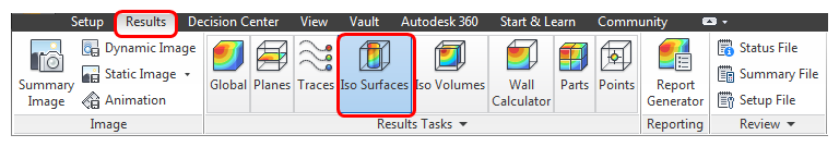
Click the Results tab.
![]()
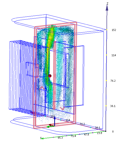
In this step, we examine the velocity results using a cutting plane and an iso surface.
Cut planes show results on a slice through the model. Use them to gain a comprehensive understanding of the flow. Use vectors to show the velocity direction and magnitude throughout the device.
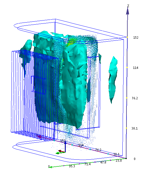
Iso surfaces show a single value of a result quantity. Use them to identify where the result quantity is very low or very high relative to the rest of the model.
Click Planes from the Results tab:
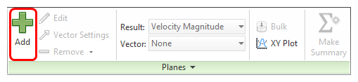
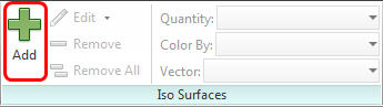
To create a Plane, click Add on the Planes context panel:
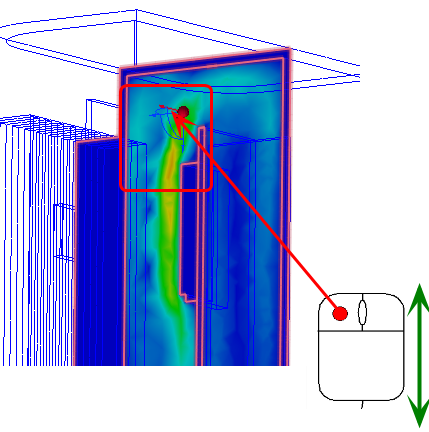
To orient the plane, left click on it, and click X from the context toolbar.
To move the plane, drag the triad axis normal to the plane.
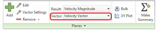
To display vectors, select Velocity Vector from the Vector menu on the Planes context panel:
To adjust the vector spacing:
- Click Edit on the Planes context panel.
- On the Plane Control dialog, drag the Grid spacing slider toward Fine. (This is near the bottom of the dialog.)
To display vectors with varying lengths (scaled with Velocity):
- Click the Vector settings tab.
- In the Length group, select Length range.
- Drag the Min slider to the left and the Max slider to the right.
To hide the contours, right click on the plane, and select Outline.
Click Iso Surfaces on the Results tab:
To create an Iso Surface, click Add on the Iso Surfaces context panel:
To change the Iso Quantity value, right click on the iso surface, and click Edit. Drag the slider on the Controls tab.
To delete the iso surface, right click on it, and select Remove