Tutorial: Centrifugal Pump
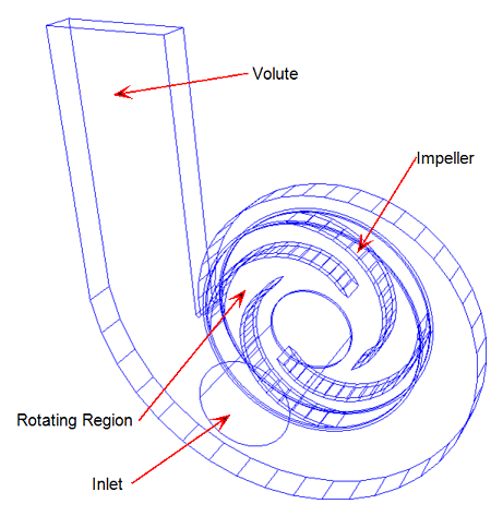
In this tutorial, we simulate the flow in a centrifugal pump with back-swept blades. The model consists of the volute, the inlet pipe, the impeller, and the rotating region:

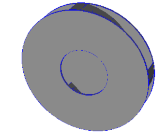
The rotating region is a volume that completely surrounds the impeller, and is the interface between rotating components and surrounding stationary objects.
This is the rotating region:

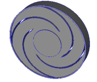
For reference, this is the impeller:

Water is the working fluid, and the impeller spins at 600 RPM. We operate the pump at the zero head state (maximum flow rate). A head loss can be imposed on the pump by assigning a positive gage pressure boundary condition to the outlet or a negative gage pressure to the inlet.
During the analysis, the impeller rotates within the stationary volute. This allows us to study the effects of the blade-pass interaction with the volute.
Approximately four complete revolutions are needed for a steady state result. At the beginning of the analysis, we will slowly ramp up the rotational speed to ensure stability and solution accuracy. Once the impeller is rotating at the desired speed, we will use a time step that causes the impeller to rotate through one blade passage per time step.
Key Topics
- Turbo Machinery analysis using a Rotating Region material
- Transient Analysis
- Non-impulsive start-up technique
- Time step size selection equal to single blade passage