Geometry Tools: Cap the Inlets
The two parts in this model are the solid parts. We use the Geometry Tools to create the internal water part by capping the openings.
Click Geometry Tools from the Setup tab.

On the Geometry Tools dialog, select the Void Fill tab.
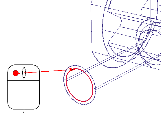
Select one of the inner edges of the first inlet.

Note: The other edge is automatically selected.
Click the Build Surface button
Cap the Cold Inlet
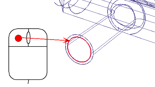
Rotate the model and select one of the inner edges of the second inlet.

Note: The other edge is automatically selected.
Click the Build Surface button
Note: As you can see, the Void fill tool creates inlet surface caps that share an edge with the solid pipe part. When solving for heat transfer, this may introduce "artificial conduction" between the solid and the fluid because of the shared edges. For the purposes of the tutorial, we are going to neglect this effect. For situations that require higher accuracy, however, an alternative approach would be to create capping parts in the CAD model or even suppress the outer pipe wall from the simulation.
For more about Void Fill Geometry tool