Transient Flows
In this context, the term "transient" refers to a time-varying flow and/or heat transfer analysis.
Initial Conditions
Initial conditions must be prescribed for transient analyses. The default condition is zero for all quantities except temperature.
To assign non-zero initial conditions:
- If the Initial Condition icon is not visible in the task bar on the Graphics window, click FilePreferencesUser Interface. Change the value for Show Initial conditions task icon to Yes.
- Click the Initial Conditions icon, and assign conditions as appropriate.
Transient Boundary Conditions
Time-varying boundary conditions are often necessary for transient analyses.
For more about transient boundary conditions
Unit of Time
Note that the time unit is always seconds for transient analyses. This unit of time is consistent with that used for the properties. Even for transients which take days or longer, the time step size should still be entered in seconds.
Inner Iterations
Because Autodesk® CFD uses an implicit method to discretize the transient flow equations, iterations must be run for every time step. This inner iteration is similar to the amount of work required for a single steady state iteration. However, the inner iterations in a transient analysis are almost always better-conditioned mathematically than a steady state iteration. For this reason, far fewer inner iterations per time step (typically 10) are required than iterations for a steady state solution.
For Rotating and Motion analyses, the recommended number of inner iterations per time step is one.
In some cases, however, increasing the number of internal iterations has helped to improve solution stability.
Divergence
If the transient calculation is diverging, the time step size will likely need to be decreased. For most situations, reducing the time step size is a better approach than adjusting the convergence controls because doing so will affect the time-accuracy of the solution. The convergence controls will artificially slow down the time history of the calculation.
Intelligent Solution Control
If invoked, Intelligent Solution Control adjusts only the time step size, and does not modify any convergence settings. This is done to prevent artificially affecting the time accuracy of the solution. (Convergence settings slow down solution progression so it is always a good idea to use the default settings for non-Motion transient analyses.)
We have found that in some cases the time step size that Intelligent Solution Control selects can be smaller than truly necessary for convergence, which may result in significantly longer solution times. For this reason, Intelligent Solution Control is disabled by default, and it is recommended to assign a time step size for transient analyses that do not involve the Advanced functionality physics.
Time Step Size
For transient flow solutions, it is important to select an appropriate time step size. A time step that is too large will result in lost detail because it exceeds the time scale of the flow. A time step that is too small will capture the flow detail, but will not be efficient because it requires more time steps than necessary to characterize the time scale of the flow.
A good guideline for the time step size is approximately 1/20th the time required for a particle of fluid to traverse the length of the device. For example, liquid travels 6 m/s through a 2 meter pipe. It takes 0.33 s for a particle to traverse the length of the pipe. Following our guideline above of 1/20th the time, use a time step of 0.0167 seconds:
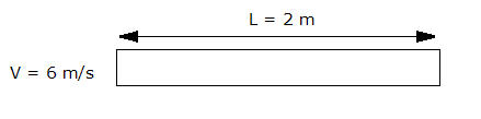
- Total Travel time = L/V = 2m / 6m/s = 0.33s
- Time step size = 0.33s x (1/20) = 0.0167s
Pressure Waves
When running a transient analysis with time-varying pressure boundary conditions, the analysis should be set to compressible. The transient terms in the pressure equations can only be accurately determined if the density is allowed to vary. Namely, pressure waves always have to be modeled as a compressible flow phenomenon.
Compressible Liquids
In water hammer analyses, the density does not vary. Compressible and Transient must still be invoked to solve a water hammer analysis.
Animation
Use the Animation dialog to animate saved iterations or time-steps.
To open the Animation dialog
- Right click off the model, and select Animation..., or
- Click Results > Image > Animation.
To animate results sets
- To select steps, click on them from the list.
- Click the Animate button.
- Use the "VCR" controls to control the animation.
- To finish animating, click the Reset button.
To save an animation
- Select the option to export an MPEG or AVI animated file.
Related Topics
For more about transient boundary conditions