Centrifugal Pump/Blower
A complement to the axial fan device, this is a material type that changes the flow direction from axial to radial. The user specifies a flow rate (constant or a fan curve) as well as an optional rotational speed.
This device models the flow through the impeller of a centrifugal device, so the volute geometry is required. Flow can also be made to enter radially/tangentially and exit axially (as in a radial in-flow turbine).
It is better to use a Centrifugal Pump/blower instead of a Rotating Region if you your focus is on moving the air within the system, and are not concerned with the physical performance of the blade design or blade-interaction effects.
To Assign a Centrifugal Pump/Blower
Open the Material quick edit dialog. There are several methods:
- Left click on the part, and click the Edit icon on the context toolbar.
- Right click on the part, and click Edit...
- Right click on the part name under the Materials branch of the Design Study bar, and click Edit....
- Click Edit in the Materials context panel.
Select one or more parts.
Select the database from the Material DB Name menu.
Select Internal Fan/Pump from the Type menu.
Select the material from the Name menu.
To specify the axis of rotation, open the pop-out dialog on the Axis of Rotation line, and select either the Global X, Y, or Z axes. To graphically set the direction, click the Select Surface button, and select a surface. The axis will be normal to the selected surface.
Select the inlet and outlet faces of the blower by opening the pop-out, clicking the Select Surface button, and selecting the surface from the blower device. This must be done for both the inlet and the outlet.
The inlet is typically the axial surface. Care should be taken when constructing the geometry that the inlet surface does not touch the outlet surface.
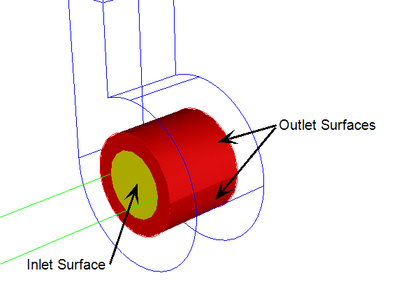
Alternatively, the device may be an annulus, like a squirrel cage. In this case, the inlet would be the interior annular surfaces, and the outlet would be the exterior cylindrical surfaces.
Click Apply.
Parts assigned a centrifugal blower material should not be extrusion meshed. The Solver does not support centrifugal blowers with extruded elements.
To Create a Centrifugal Pump/Blower
- To open the Material Editor, click Material Editor on the Materials context panel.
- Click the List button.
- Right click on a custom database, and select New material. Select Centrifugal Pump/Blower. Specify a Name.
- Click the property button that is to be defined.
- For each property: Select the Variation method, enter the appropriate value and units, and click Apply.
- Optionally, click Save.
- Click OK. The new material is available when the Materials quick edit dialog is opened.
The Default material database contains at least one instance of every material type. A convenient way to create a new material is to use a Default material as an example. Because these materials are read-only, use the Material Editor to copy the original into a custom database, and modify the copy. For more about creating a material from an existing material...
Guidelines
- The Flow Rate and the Rotational Speed are necessary inputs. The specific direction of flow and rotational direction are not part of the material definition. These settings are entered on the Material task dialog, making them particular to the assigned geometry.
- No other fluid property information is required to define a centrifugal pump. The Solver automatically applies the fluid property information from the surrounding fluid to the pump. For this reason, it is very important that a pump contact only one fluid material type.
Properties
Flow Rate
There are two methods for specifying the flow rate: as a constant value and with a fan curve.
Constant:
Enter the Flow Rate Value and the appropriate units.
Fan Curve:
Enter the Flow Rate and Pressure Head data into the table. This information often comes from fan manufacturer data. Data in “.csv” format can be imported using the Import button. Data is saved to a “.csv” file using the Save button.
Rotational Speed
The rotational speed is an optional parameter, and can only be entered as a constant value.