Motion
The Autodesk® CFD Motion Module provides the ability to analyze the interaction between solid objects in motion and the surrounding fluid. The effect of the motion on the fluid medium as well as the flow-induced forces on the object can both be analyzed efficiently and quickly.
There are seven motion types:
- Linear
- Angular
- Combined Linear/Angular
- Combined Orbital/Rotational
- Nutating
- Sliding Vane
- Free Motion
For all but two of these, either input parameters or the flow defines the motion. (Sliding Vane is user-prescribed only, and Free Motion is flow-driven only.)
Define motion by specifying only the applicable properties and directions, as opposed to all six degrees of freedom. The displacement, velocity, or location of objects in motion is either explicitly prescribed or is driven by the forces imparted from the surrounding flow. In the case of the latter, externally applied driving and resistive forces (such as springs) can be defined that influence the motion of the object.
Parts with assigned motions are color-coded in the display window for clarity.
Motion Task Visibility
By default, the Motion command is not included in Setup (tab) > Setup Tasks (panel) or the Design Study Bar. To enable it:
- Click the Application Menu button (in the top left corner).
- Click Options.
- In the Display tab, change the setting for Show motion task icon to Yes.
For an example of enabling the Motion task dialog
Motion Workflows
Only objects that are solids (as assigned on the Materials dialog) can be assigned motion. Solids are shaded while the Motion task is active. All parts with non-solid materials appear in outline mode. The basic Motion work-flows are summarized:
To begin, click Setup (tab) > Setup Tasks (panel) > Motion or Motion from the Design Study bar.
To work close to the model:
- Left click on the model entity (surface or part).
- Click the Edit button on the context toolbar.
- Specify settings in the Motion quick edit dialog.
To work away from the model:
- Left click on the model entity (surface or part).
- Click Edit from the Motion context panel,
- Specify settings in the Motion quick edit dialog.
To specify settings in the Motion quick edit dialog
- Select the Type of motion. The choices are: Linear, Angular, Combined Linear/Angular, Combined Orbital/Rotational, Nutating, Sliding Vane, and Free Motion.
- Click the Edit button. This opens the Motion Editor for defining the motion.
- Set the needed Axes, directions, Center of Rotation (or Center of Nutation). Pop-out dialogs contain controls for graphical selection of these values.
- Set an Initial Position, if needed.
- If the motion is flow driven, check the Flow Driven box, and set the Bounds as necessary.
- Preview the motion by clicking the Preview button.
- Click Apply to finish the command.
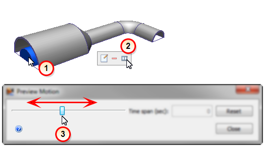
Previewing Motion
After assigning a motion to a solid part, it is always a good idea to preview the motion to ensure the expected result. To open the Preview Motion dialog, either click Preview from the Motion context panel, or click the Preview icon from the Motion context toolbar (shown below).
- To preview the motion of a specific part, left click on the part, and open the Preview Motion dialog.
- To preview the motion of all moving parts, open the Preview Motion dialog but do not select any parts.
To preview the motion, drag the slider on the Preview Motion dialog.
The time span is computed based on the motion definition. A pseudo-time span is used for flow-driven motion.
Groups of Motions (Linked Motions)
In many devices, two or more objects that are driven by the flow are physically connected in some manner so that their motions are related. Examples include
- Hydraulic rams that slide linearly together through multiple cylinders
- Gears in a gear pump rotate in opposite directions at the same rotational speed
Because of a mechanical linkage between the object, the motion of one is dependent on the motion of the others.
To link the motion of two or more objects, use the Group functionality to add the parts whose motions are to be linked. When creating the group, select Motion as the type on the Group Creation dialog.
Grouping is only applicable to flow-driven motions that are assigned the same motion type. If a linear and an angular motion are grouped together, for example, the linking is not possible, and will hence be ignored.
The linking functionality depends on the direction(s) of motion for the relevant parts being fully defined. Objects with linked motions can move in different directions or even rotate in opposite directions. In the case of a gear pump, for example, the two gears rotate in opposite directions from one another. Assign the directions for both objects as appropriate, and add the two motions to the same group. As the flow moves them, they will move with the same rotational velocity, but in the assigned directions.
Related Topics
The following topics contain additional information about simulating motion with Autodesk® CFD.