Combined Orbital-Rotational Motion
Combined Orbital/Rotation motion is another combination motion mode--the object rotates about its axis of rotation, and also orbits about an axis parallel to its axis of rotation. Rotational motion is described in the Angular Motion section of this chapter.
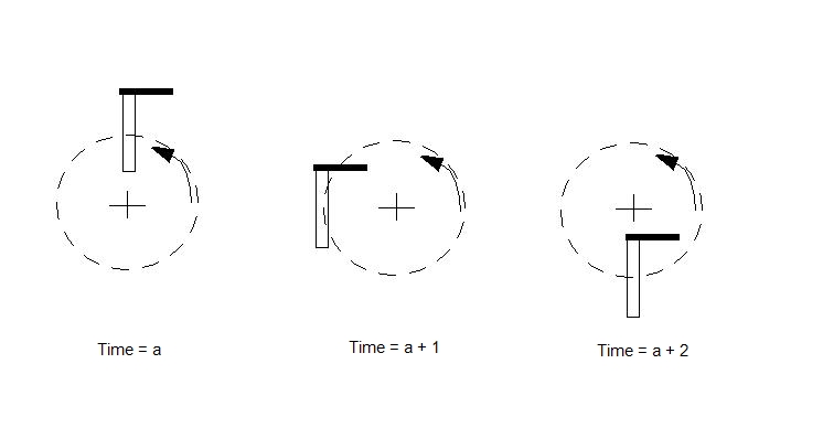
Orbital motion is the circular displacement of an object about an axis. The orientation of an object in pure orbit (with no rotational component) does not change. This is shown below:
The combined rotation and orbital motion is shown below (in this graphic the rotation and orbital speeds are the same):
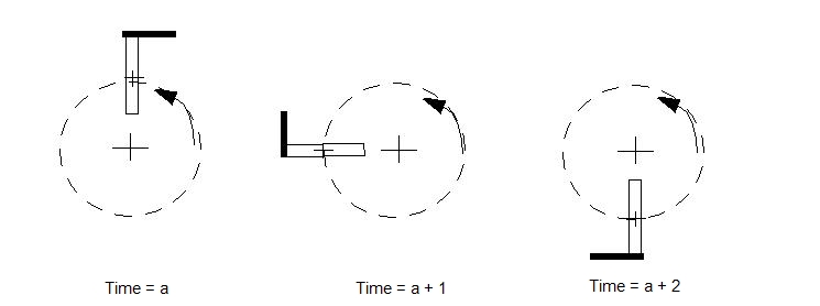
The orbital speed is usually slower than the primary rotational speed.
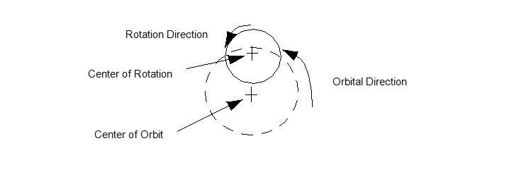
A typical application for Combined Orbital/Rotational motion is a pump shaft with an eccentric orbit (or whirl) component. The shaft rotates about its centerline, but also has an eccentric rotation about an additional axis.
By specifying an orbit on an object, it is possible to understand the force imbalance imparted on bearings and other fixtures as a result of a shaft orbit:
Both motions can be either user-prescribed or flow-driven. If the orbit is flow-driven, then the forces acting on the moving object are summed and appropriate accelerations are computed. Velocities and displacements are limited to the circular orbital path using the following relationships.
The two elements of Orbital motion, the rotation and the orbit, are defined independently as User-Prescribed or Flow-Driven. The Flow-Driven check boxes on the Motion task dialog govern how each element is defined on the Material Editor. The possible combinations of user-prescribed and flow-driven are listed:
- User-Prescribed Rotation/User-Prescribed Orbit
- Flow-Driven Rotation/User-Prescribed Orbit
- User-Prescribed Rotation/Flow-Driven Orbit
- Flow-Driven Rotation/Flow-Driven Orbit
The following sections describe how to set up User-Prescribed and Flow-Driven Orbital motion. The variation methods described are applicable to the two user-prescribed/flow-driven combinations: