Assigning Free-Motion
- Select one or more objects.
- To open the Motion quick edit dialog, click Edit on the Motion context panel.
- Select Free Motion as the Type.
- Click Edit... on the Edit Motion line. This opens the Motion Editor. Specify the initial linear and angular velocities of the object.
- Specify the applicable Free Motion Parameters: Active Degrees of Freedom (DOF), Applied Force, and Gravity.
- Click Apply.
Active Degrees of Freedom
By default, objects in free motion can move in any direction. Expand the Active DOF menu to view the six degrees of freedom. There are two type of degrees-translation and rotation. None of the components are enabled by default, meaning that movement is prevented in all directions and about all axes.
Check a degree of freedom to allow translational motion in that direction or rotational motion about that axis.
For two-dimensional models, the Z translation, X and Y rotations are inactive because motion in these directions is not possible for models oriented in the xy plane.
Translation
Use the Minimum and Maximum pop-out dialogs to set the bounds of motion. Bounds can be set by keying in a bounding position or using the slider on the pop-out dialog to graphically set the position. The default state is that the motion is unbounded.
- To key-in a location in the field, click in the field, and specify the desired coordinate. For example, if 1.5 inches is entered as a minimum value, then the object can not go beyond 1.5 inches in the negative direction of travel. This distance is relative to the initial position of the object.
- To specify the value graphically, use the pop-out dialog to position the plane at the desired boundary with the slider. The graphical plane moves normal to the direction of travel. All locations are relative to the initial position.
The Min and Max boundaries can be specified using different methods.
Rotation
Use the minimum and maximum fields to set the bounds of rotation. Bounds can be set by keying in an angular bounding position or using the slider on the pop-out dialog to select an angular position. The default state is that the motion is unbounded.
The minimum and maximum boundaries can be specified differently, if necessary.
- rotation only around the x with min-max angular limits
- rotation only around the y with min-max angular limits
- rotation only around the z with min-max angular limits
- rotation about all 3 axes, but only integrating around active axes - angular limits are not imposed
Applied Force
This set of controls provides a way to specify an optional force acting on the object. There are three basic parameters required to specify a force on an object in free motion: The Force Direction, the Force Magnitude, and the Location of force application on the object:
Force Direction
The Force Direction is specified by either keying-in a direction vector, or using the pop-out dialog to select a Cartesian direction or a surface that is normal to the force direction.
It is necessary to select the Type of force application. This can either be a Constant Vector or Vary by Orientation with position of the object.
Constant Vector
If Constant Vector is selected, the direction of force will not change even as the object orientation changes. The force direction remains constant, even if the object rotates about an axis. This is shown:
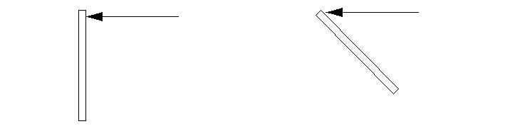
On the left, the initial position is shown. Force is applied in the negative x direction.
On the right, the object rotates because of the torque about the object center. Force is still directed in the negative x direction. The resultant torque will vary as the the object changes orientation.
Vary by Orientation
If Vary by Orientation is selected, the direction of force will vary relative to the coordinate system, but will remain constant relative to the object. This is the recommended way to apply a constant torque to an object in motion. This is shown:
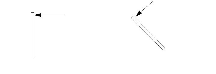
On the left, the initial position is shown. Force is applied in the negative x direction.
On the right, the object rotates because of the torque. The force is constant relative to the object, but varies relative to ground. The resultant torque remains constant as the object moves.
Force Magnitude
Select if the force is Steady State or if it is Transient from the Time Dependent line.
If the force is steady state, enter the value in the Magnitude field. If the force is transient, open the pop-out dialog to specify a piece wise linear relationship between force and time.
Be sure to select the units of force in the Unit field.
Location
The final step is to specify the location of the applied force on the object. There are two methods: Key-In a location or open the pop-out dialog, and select a planar surface. The centroid of the surface will be the point of application of the force.
This point must be on or in the moving object. A specified point of application that does not contact the object in its initial location will cause the force to not act on the object throughout the analysis.
Gravity
The Gravity menu allows for specification of a gravitational acceleration to act on the object. Expand the Gravity menu, and check the Earth box to indicate that the object is subjected to the Earth’s gravitational pull. Enter a unit vector to indicate the direction of the gravitational force (or select one graphically using the pop-out dialog).
To define a gravitational pull that is different from that of Earth, uncheck the Earth box, and enter the gravitational acceleration in the appropriate direction. The units of this value will be in terms of the analysis length unit.