Heat Sinks
Use heat sink materials to simulate the performance of your heat sink components with geometrically simple models. When your models contain heat sinks with large aspect ratios (the ratio of fin height to fin spacing), meshing of such components requires many elements. In such cases, the number of elements can render a full system analysis expensive and unwieldy, if the analysis can be undertaken at all.
Modeling considerations
When deciding whether to use heat sink materials, consider the following:
- Heat sink materials use correlations to approximate the detailed modeling of the heat sink. The correlations, based largely on experimental results of fully shrouded heat sinks, provide more rapid results allowing you to make predictive design decisions. Learn more about the correlations and governing equations.
- You can use heat sink materials for non-shrouded heat sinks, but expect conservative results (higher component temperatures).
- The correlations do not account for the effects of flows that are not predominantly normal to the model approach surface.
- If you have many heat sinks and/or heat sinks with large aspect ratios, the number of elements grows quickly making a heat sink material more advantageous.
- Heat sink correlations are based on the assumption of laminar flow within the heat sink.
- Heat sinks must be cuboid in shape and fully immersed in a fluid.
- Heat sinks can interface with more than one chip part and do not have to have the same footprint as the chip.
- Heat sink materials support natural convection, but require you to guess the approach surface under such conditions.
- The chip part, with which the heat sink material interfaces, must be a meshed solid part. That is, the chip part cannot use materials such as Compact Thermal Model (CTM), Thermoelectric Component (TEC), heat exchanger, and so forth.
- You cannot apply boundary conditions to the approach or outlet surfaces of the heat sink. You can apply boundary conditions to the exterior side surfaces.
Correlation requirements
To ensure valid use of heat sink materials, the physical geometry of your heat sinks and the operating conditions are subject to certain requirements:
Micro Channel:
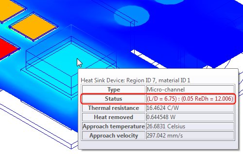
Channels are sufficiently long such that flow is fully developed for 95% of the channel length:
- L/Dhch > 0.05ReDhch; where L = channel length, Dhch = channel hydraulic diameter, and ReDhch = Reynolds number of the channel.
- L/Dhch > 0.05PrReDhch; where L = channel length, Dhch = channel hydraulic diameter, Pr = Prandtl number, and ReDhch = Reynolds number of the channel.
Channel height to width ratio of 4+ :
- Hch/wch > 4; where Hch = channel height, and wch = channel width.
Ratio of solid conductivity to fluid conductivity of 20+ :
- ks/kf > 20; where ks = solid conductivity, and kf = fluid conductivity.
Pin-Fin:
Prandtl Number greater than or equal to 0.71:
- Pr >= 0.71
Reynolds number between 40 and 1000:
- 40 <= Redcp <= 1000; where Redcp = Reynolds number based on the pin diameter.
Approach velocity between 1 and 6 meters/sec:
- 1 m/s <= U <= 6 m/s; where U = velocity at inlet of heat sink (m/s).
Pin diameter between 1 and 3 millimeters:
- 1 mm <= d <= 3 mm; where d = pin diameter.
Ratio of the longitudinal (flow direction) pin spacing to the pin diameter between 1.25 and 3:
- 1.25 <= SL/d <= 3; where SL = longitudinal pin spacing and d = pin diameter.
Ratio of the transverse (normal to flow direction) pin spacing to the pin diameter between 1.25 and 3:
- 1.25 <= ST/d <= 3; where ST = transverse pin spacing and d = pin diameter.
Offset Strip:
Gases and liquids with moderate Prandtl Number.
Choosing your model type
You represent the physical heat sink using one of two model types: single-part or two-part. If the fins on your actual component attach to a thin base material, use a single-part model; otherwise, a two-part model is appropriate. How do we distinguish between the thin and not-thin? Your base is thin if the thickness is a small percentage of the overall component height and the base has an insignificant flow impact.
Single-part model characteristics
- Geometry consists of a simple block with the same envelope as the actual component.
- Base plate is thin and has insignificant impact on flow characteristics.
- Footprint of the block is the same as the associated chip.
- Associated chip must be a solid material type - for example, it cannot use the Compact Thermal Model type.
- Chip and heat sink are in direct contact.
Two-part model characteristics
- Geometry consists of simple blocks with the same envelope as the base plate and fin area, respectively.
- Base plate is thick and impacts flow characteristics.
- Footprint of the base plate and block is larger than the associated chip.
- Associated chip uses the Compact Thermal Model type.
- Heat sink interfaces with multiple chips.
Setting up your model
Once you choose the model type, single- or two-part, you create the model geometry and define the material properties to properly simulate the actual component.
Geometry
Replace your heat sinks with simple cuboid solids in your CAD model. The solids have the same envelope dimensions as the heat sinks. If you choose the two-part model, two solids represent each heat sink - one for the base area and one for the fin area.
Base thickness
The heat sink material model correlations use the base thickness to determine heat transfer through the base plate.
- For a single-part model, specify the actual base thickness.
- For a two-part model, since you are modeling a simple block solid to represent the base plate, specify zero. A non-zero value results in additional simulated base plate thickness in excess of your block thickness.
Base conductivity
Enter the base plate material conductivity.
Fin conductivity
Enter the fin material conductivity.
Type
Select the Variation method most like the configuration of your heat sink. Then, enter the associated Fin parameters.
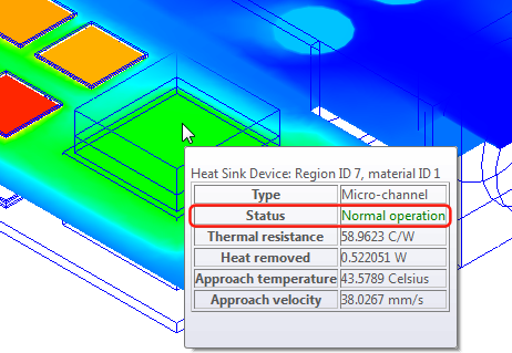
Verifying model usage
After your analysis, view results associated with your heat sink components to ensure that the heat sink material geometry and flow conditions are valid. Status = Normal operation indicates acceptable use of the heat sink material. Otherwise, the Status line provides information as to why the material is invalid for the operating conditions.
You have two methods for checking the status of your heat sink materials.
You can view the heat sink status in the summary file. Click Summary File in the Review context menu to view the summary.
Pause the cursor over your heat sink material. A tooltip appears providing the status and some operating results for the material.
 Note: During the initial iterations, it is possible for your heat sink material tooltip to reflect abnormal operation even though the geometry and operating conditions are acceptable. Wait for your analysis to exceed 100 iterations before evaluating the status value.
Learn more about assigning and creating heat sink materials.