Materials in AEC Applications
Air is the primary physical material used in most AEC applications. Each application topic (Mechanical, Natural Ventilation, and External) describes the specific details about how Air should be used for specific application types.
Solid materials are often frequently used to simulate building materials and other physical solids. Material devices such as Internal Fans and Distributed Resistances provide a convenient way to simulate complex devices (fans, filters, baffles, etc.) with simple geometry. This topic describes the details of using Solid materials, Internal Fan devices, and Distributed Resistance devices for AEC models.
Solid Materials
The Default material database includes a wide variety of solid materials. The following are often used in AEC applications:
- Brick
- Gypsum Board
- Hardwood and Softwood
- Steel
- Glass
Custom Materials
Several additional material types are also typically used in AEC applications, but due to the large number of varieties, are not included in the Default Material library. Examples of such solids include:
- Concrete
- Soil
- Insulation
- Composites
Use the Material Editor to create additional materials and save them into a custom material database.
For more about creating custom materials...
Equivalent-Property Materials
A useful way to reduce model complexity is to use a single part that is thermally equivalent to a complex assembly. Some examples include:
Double pane window--specify the following properties that are equivalent to the sum of the glass and interior gas layers:
- Thermal conductivity
- Density
- Specific heat
Human--specify the properties of water to represent the thermal properties of a human being.
Internal Fan Material Devices
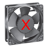
Internal Fan devices use very simple geometry to move air flow within a room or structure. Their simplicity allows us to simulate the effects of a fan without modeling physically rotating blades. Specify the flow either as a constant flow-rate or with a fan characteristic curve (PQ curve).
One of the most common applications for Internal Fan devices is to simulate air movement within a server rack assembly in a data center. Instead of modeling every fan within a rack, use a single fan device that delivers the equivalent flow of all of the smaller fans.
Basic Fan best practices for AEC applications
- To model Internal Fans, do not model the actual fan geometry. Instead, use either simple cylinders, annular rings, or six sided blocks (if modeling a server rack assembly).
 |  |
It may be difficult to mesh a fan that is modeled with extremely thin geometry. Ensure the thickness of the part is at least one-third its diameter.
In addition to the flow rate, assign a rotational speed and a slip factor. Slip factor is the ratio of the rotational velocity of downstream air to the blade rotational speed. Typical axial fans have a slip factor between 0.3-0.5. Both rotational speed and slip factor are optional parameters.
Do not allow adjacent fans to touch one another. Ensure a layer of air is between adjacent fans.
Do not assign flow boundary conditions to fans.
If there are no convenient heat-dissipating parts within the rack, represent the heat generated by server components by assigning either a Heat Generation or Total Heat Generation to the fan part.
For more about creating, applying, and using internal fan devices...
Distributed Resistance Material Devices
Use the distributed resistances material device to simulate the flow through complex, but regular, geometric obstructions. Their simplicity allows to represent the pressure drop caused by such obstructions using geometrically simple representations.
Resistance applications in AEC simulations
There are numerous occasions to use distributed resistances in AEC applications. They are extremely useful for applications involving HVAC systems, Datacenters, and Lab spaces. Some specific model elements include:
- Screens
- Filters
- Baffle assemblies
- Heating and cooling elements
- Crowds of people (seated or standing)
- Trusses
- Exterior landscaping
Resistance methods for AEC applications
There are several ways to define a resistance. Click here for more about distributed resistance methods...
The quickest and most commonly used method for AEC is the Free Area Ratio. This is a geometrically-derived representation of the percentage of open area to the total area of an obstruction:

Use the free-area ratio method for obstructions such as perforated plates or baffles in which the open and total areas can be conveniently computed.

For more about free area ratio resistances...
An alternative method commonly used in AEC applications is the Head capacity curve. This method computes pressure drop using a table of pressure-drop and flow rate data.
Use this method if the load curve data (pressure drop as a function of flow rate) is available for the obstruction.

For more about head-capacity curve resistances...
Basic Resistance best practices for AEC applications
- To model a complicated component, replace the part in the CAD model with a simple cuboid (or other appropriately shape) object. (This should be part of the model preparation process before transferring the model into Autodesk® CFD.)
- Do not assign flow boundary conditions to distributed resistances.
- To represent the heat generated by server components if there are no convenient heat-dissipating parts within the rack, assign either a Heat Generation or Total Heat Generation to the resistance part.
- To model a very thin item such as a perforated metal screen over a floor vent or diffuser, use a surface material instead of a volume. To do this, assign the resistance material to the surface representing the screen and leave the neighboring volumes assigned as air. For more about surface parts...
For more about creating, applying, and using distributed resistances...