Assess Parts with the Model Assessment Toolkit
When you set up your CFD simulation from a CAD model, various part and assembly geometry issues can negatively impact the mesh completion or mesh quality. For parts, the MAT assesses three geometry situations and provides you with the resulting data and settings to aid your investigation. Use the MAT and your engineering judgment to determine the importance of potential issues and plan for any needed remedies. Once you find issues, return to your CAD application and modify the geometry appropriately.
The following image shows a frame assembly model as transferred from Autodesk® Inventor into the MAT. Let's use the different part tools to assess the model and provide examples of part geometry configurations you might consider when evaluating potential issues.

Edge Lengths
Small part edges require fine mesh seeding which can significantly increase mesh counts. Small edges can also introduce local discontinuous behavior in the mesh length scales which negatively impacts solution accuracy. Use the Edge Lengths tool to assess your model for potential small edge issues.
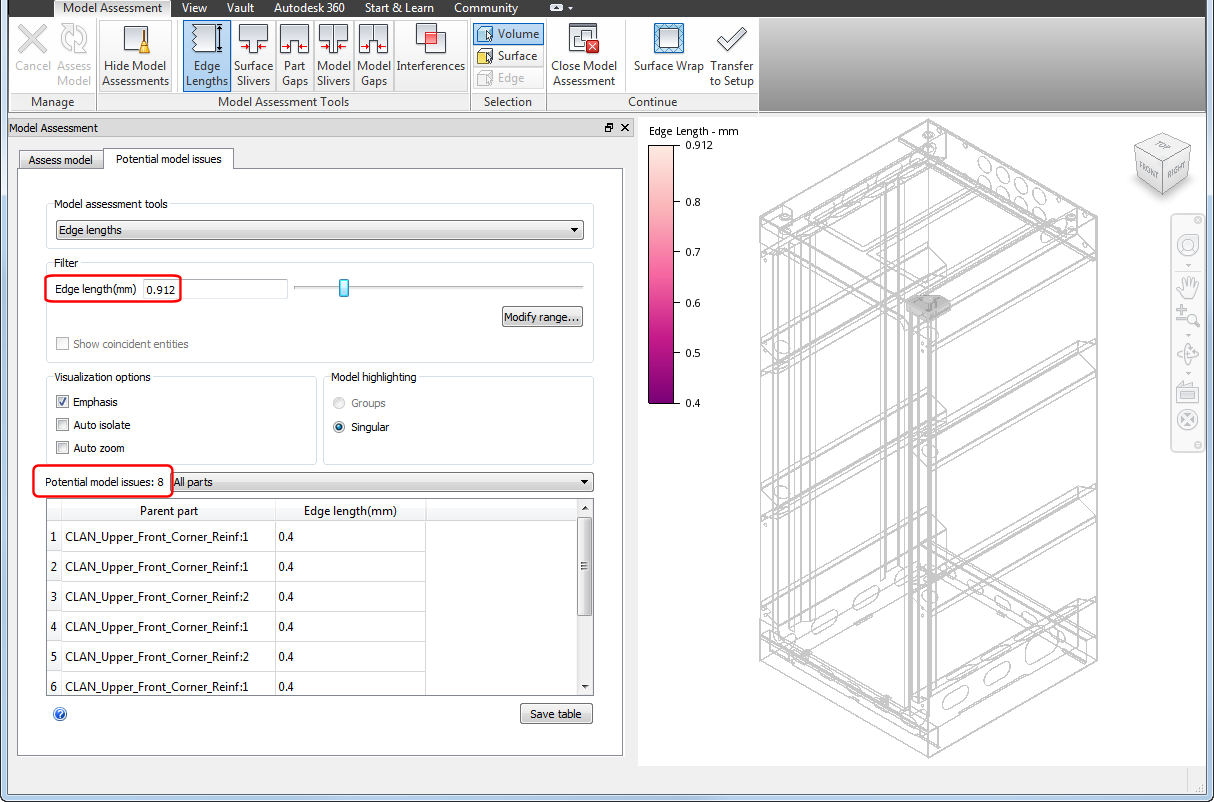
The following image shows our frame assembly model with the Edge Lengths tool active. Given the initial edge length filter setting of 2 mm, you see 780 potential edge length issues.
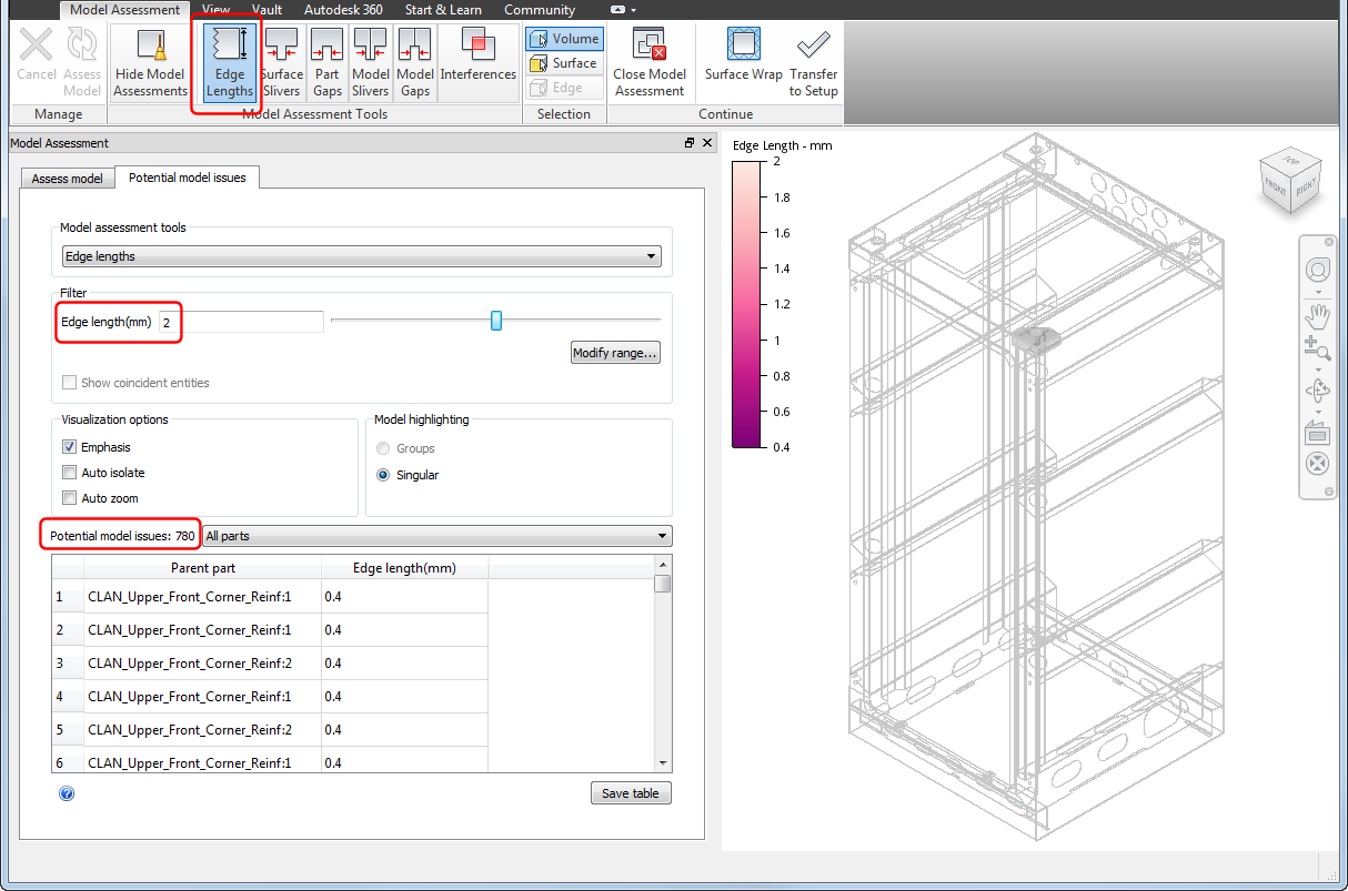
However, a quick scan of the issues table shows all but eight edge lengths are at, or above, 1 mm. So, by adjusting the Edge length slider to less than 1 mm, we eliminate all but eight issues from the table.
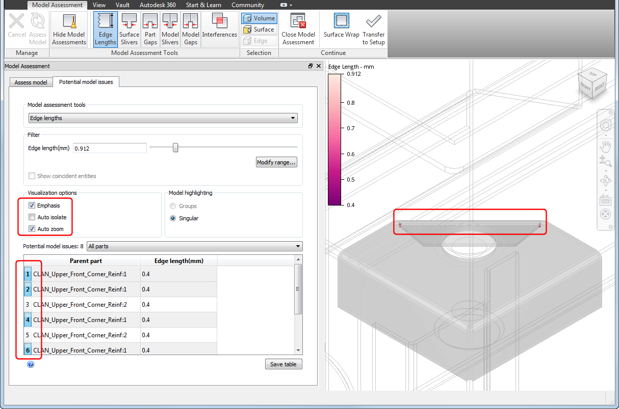
When you select the table entries and select Auto zoom and Emphasis, you see four of the potential edge length issues on the corner bracket.
By rotating and zooming the view, we see 2 of the potential edge issues on the corner bracket where the bend and chamfer occur.
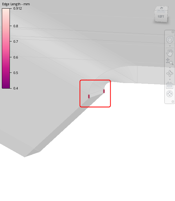
Most likely, the short edge length is not important relative to the simulation . As a result, we can return to Inventor and remove these edges to avoid high mesh density.
Surface Slivers
Similar to short edges, small surfaces on parts can also result in mesh length scale issues. Use the Surface Slivers tool to assess your model for small surfaces that may challenge the CFD mesher.
Returning to our model and using the Surface Slivers tool with a filter size just over 0.4 mm, we find eight surface issues on the corner brackets.
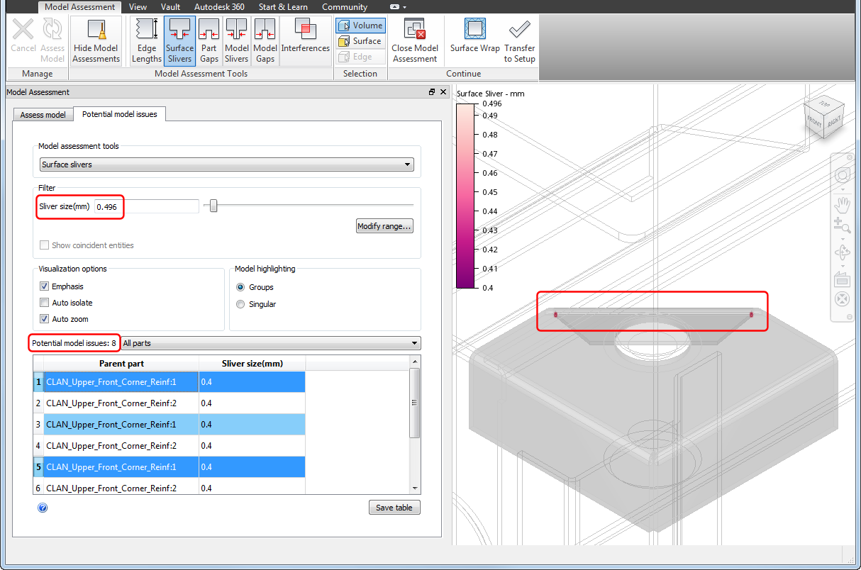
When we manipulate the view to find those surfaces, it is no coincidence that the surfaces correspond to the short edge lengths we previously located.
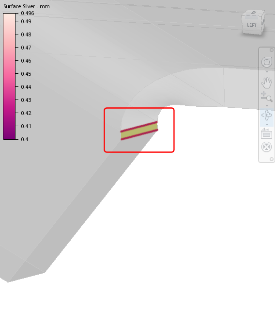
As with the short edges, modeling these small surfaces is, most likely, not important relative to the simulation. As a result, we can return to Inventor and remove these surfaces to avoid high mesh density.
Part Gaps
Similar to short edges and small surfaces, small gaps between surfaces on a part can result in mesh length scale issues. Use the Part Gaps tool to assess your model for small gaps that may challenge the CFD mesher.
Returning to our frame assembly model and using the Part Gaps tool we find sixteen gap issues on the two corner brackets.
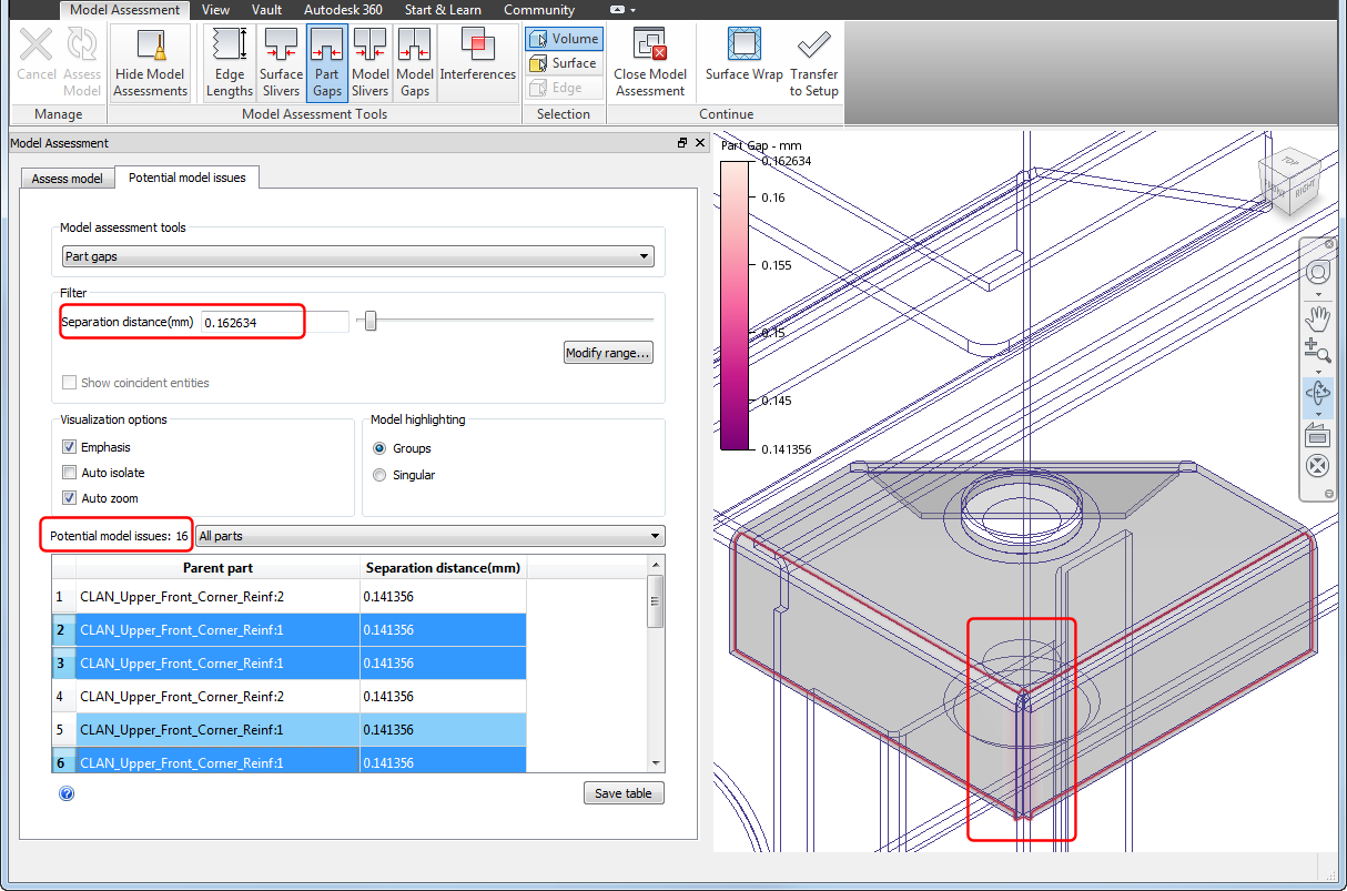
When we manipulate the view to find the gaps, we see they occur where edges of the brackets nearly touch.
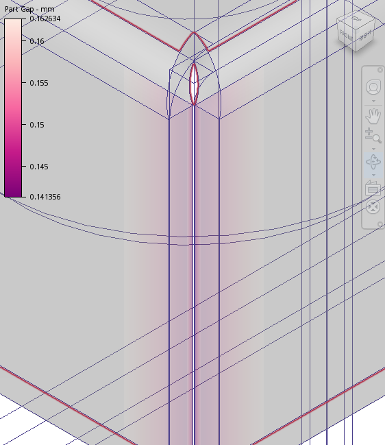
Modeling these small gaps is, most likely, not important relative to the simulation. As a result, we can return to Inventor and eliminate the gaps to avoid high mesh density.
Reworked Part
Upon returning to Inventor, we made small changes to the bracket chamfer and corner, as shown in the following images.
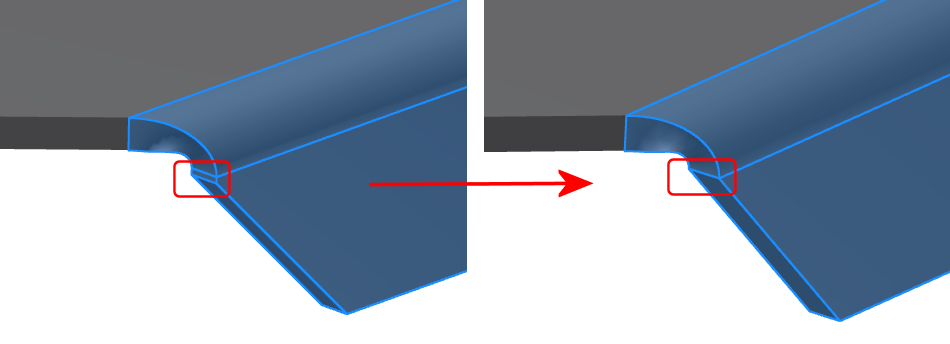
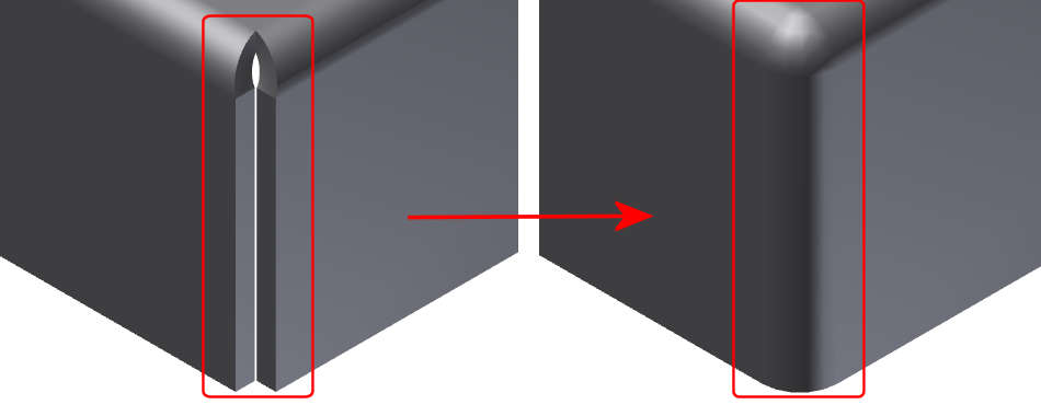
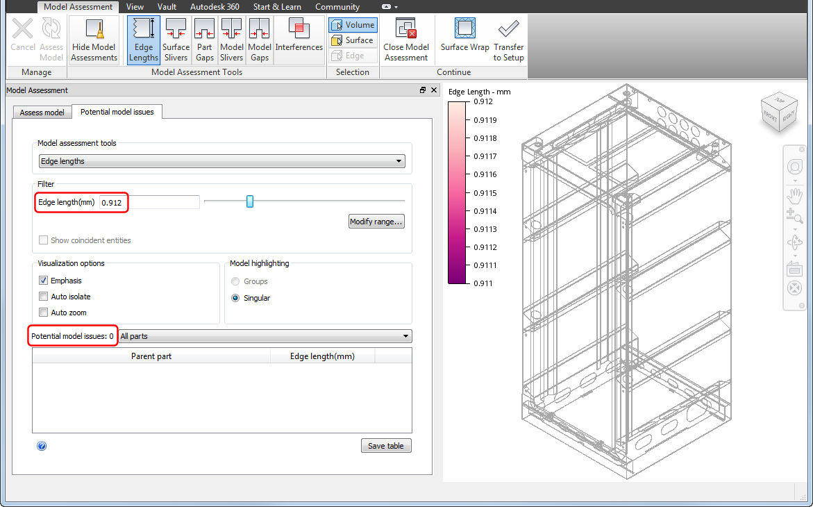
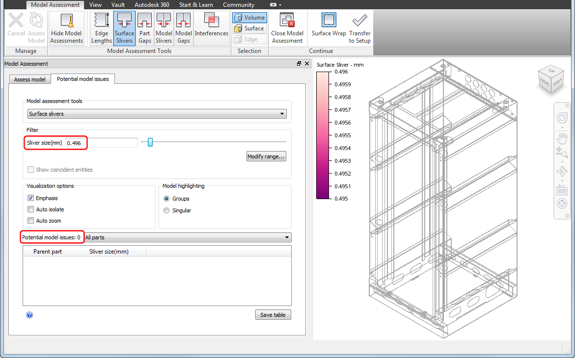
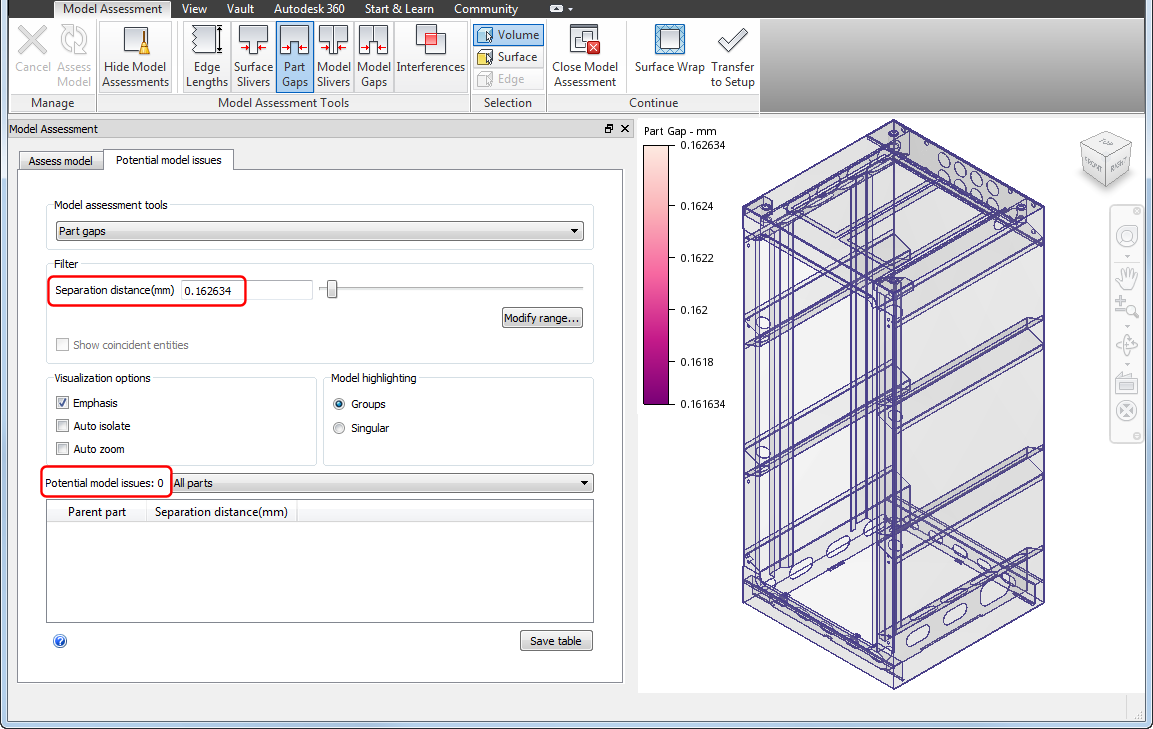
Once the brackets updated in our assembly, processing in the MAT produces the following results. The filter settings are the same as the settings that previously yielded potential issues in the respective tools. Now, following the small CAD operations, those potential issues are eliminated. The improvements result in a better mesh about the bracket and more effective simulation.
